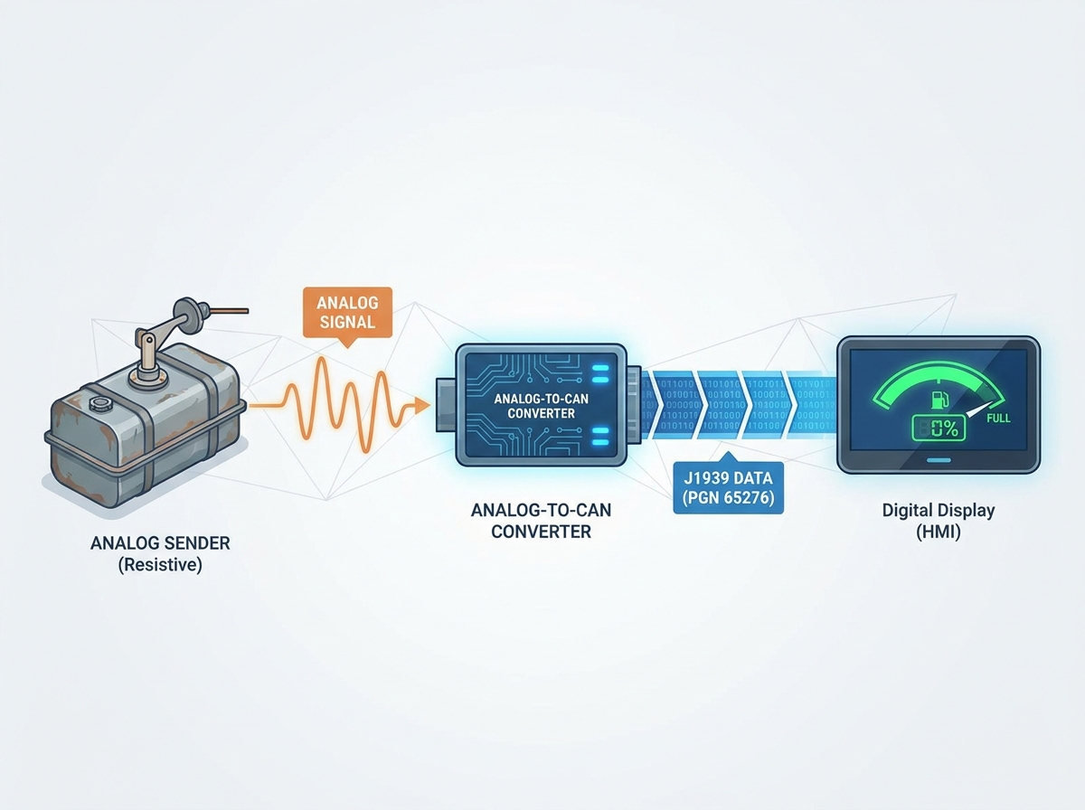
You have recently upgraded to a modern digital display like a Garmin, Murphy, or custom Human-Machine Interface (HMI). You expect crystal-clear engine telemetry and precise data readouts. Instead of clear readings, the fuel gauge flashes an error, reads zero, or remains entirely blank. This frustrating scenario halts operations instantly and leaves operators completely blind to their fuel reserves.
In SAE J1939 and CAN bus networks, a missing fuel level is rarely a broken screen. It is almost always a failure in hardware communication, a protocol mismatch, or an analog-to-digital translation error. Modern digital displays expect tightly regulated data packets. If the data packet is missing, corrupted, or sent at the wrong speed, the gauge simply fails to populate.
This guide breaks down the root causes of a missing J1939 fuel signal. You will learn how to isolate faults between the physical wiring and the data link layers. Furthermore, we outline the strict criteria for selecting the right replacement sensor or analog-to-CAN converter. You can use these insights to restore network stability swiftly.
Key Takeaways
A J1939 fuel level not showing on the display usually stems from missing termination resistors, mismatched baud rates (250k vs. 500k), or a failure to broadcast PGN 65276 (SPN 96).
Upgrading an older engine to a digital HMI requires a specialized analog-to-CAN converter if the original resistive sender is retained.
When evaluating a new SAE J1939 tank level sender, prioritize units with configurable source addresses and ruggedized IP67+ ratings for harsh environments.
Resolving this issue systematically prevents unnecessary replacement of fully functional digital displays.
The Business Cost of a J1939 Fuel Level Not Showing
Heavy-duty trucks, marine vessels, and industrial power generators rely heavily on precise telemetry data. Operating without accurate fuel data creates immense operational risk across all these sectors. You face catastrophic fuel runouts in remote locations and unexpected downtime during critical operations. Diesel engines are especially vulnerable to fuel starvation. Running a massive diesel tank completely dry often causes severe system air-locks in the injection system. Bleeding the high-pressure fuel lines requires extensive mechanical intervention, forcing the asset offline for hours.
Operators often point fingers at the expensive digital display when gauges fail. They mistakenly blame the sophisticated HMI screen when the actual failure lies hidden deep within the wiring. In many cases, you will find a simple wiring harness fault causing the outage. A misconfigured network node or a corroded pin can also cause the exact same blank screen. Blaming the screen leads to wasteful diagnostic testing and endless frustration for maintenance crews.
A successful fix establishes continuous, stable fuel data broadcasting across the entire bus. The network must send data on the correct identifier without hesitation. You should see absolutely no network collisions on your diagnostic tools. The system must completely eliminate any constant disconnect or timeout errors. Achieving this ensures highly reliable operations and restores operator trust in their digital gauges.
Physical Layer vs. Data Link: Diagnosing the Disconnect
Diagnosing why you have a J1939 fuel level not showing requires splitting the network into two distinct halves. You must evaluate the physical wiring hardware and the digital protocol software separately. Mixing up these troubleshooting steps wastes valuable diagnostic time.
Isolating the Physical Layer (Wiring and Hardware)
The physical layer carries the raw electrical impulses between controllers. If this foundation fails, no digital data reaches the display unit.
Termination Resistors: CAN networks strictly require 120-ohm resistors at both ends of the main backbone. Missing resistors cause severe signal reflection along the wiring. This reflection scrambles data packets and drops the fuel data entirely. Always use a digital multimeter to measure resistance across CAN High and CAN Low. It should read approximately 60 ohms when the system is powered down.
Harness Integrity: Inspect the wiring routing carefully along the chassis or hull. Check for pinched CAN High or CAN Low wires near bulkheads. You must also verify the main ground connections at the sensor head. A compromised ground creates electrical voltage offsets. These offsets prevent the transceiver chip from reading differential signals correctly.
Connector Corrosion: Check the connectors for green oxidation. Water ingress at the plug ruins the delicate CAN voltages. Clean the pins thoroughly and apply dielectric grease to prevent future moisture buildup.
Isolating the Protocol Layer (Data and Software)
If the wiring tests perfectly sound, the issue usually hides in the data layer. Software misconfigurations are incredibly common during aftermarket equipment upgrades.
Baud Rate Mismatches: Network nodes must speak at the exact same speed. If your main engine network runs at 500 kbps, but the replacement sensor broadcasts at 250 kbps, communication fails instantly. The display cannot parse the slower data packets. You will see blank screens or severe communication timeout errors on the dash.
PGN and SPN Verification: The standard industry identifier for Dash Display fuel level is Parameter Group Number (PGN) 65276. This specific message utilizes Suspect Parameter Number (SPN) 96. You need a dedicated CAN analyzer tool to verify this. Plug it into the diagnostic port and watch the live traffic. If PGN 65276 is missing, the sensor is simply not sending it.
FMS Gateway Filtering: Fleet applications often use a Fleet Management Standard (FMS) gateway module. This gateway safely separates the critical engine bus from the telematics reporting bus. Ensure the gateway is not actively filtering out the fuel level PGN before it ever reaches the dashboard display.
The Retrofit Challenge: Bridging Analog Senders to Digital Displays
Older diesel engines rely on very simple, decades-old technology for fuel measurement. They typically use resistive analog senders built around a sliding mechanical float. These senders output raw variable resistance ranges like the American standard 240-33 ohms or the European standard 0-190 ohms. Modern J1939 displays only understand sophisticated digital packets. They cannot read this raw electrical resistance directly, creating a fundamental hardware incompatibility.
Solution Category: Analog-to-CAN Converters
You might not want to drain a massive industrial tank immediately. You can choose to leave the existing analog unit fully in place. An analog-to-J1939 gateway can digitize the existing analog signal. This small, inline module acts as a smart translator between the old sender and the new digital display. It reads the resistance and converts it into a valid CAN packet.
However, you must exercise extreme caution during the procurement process. Avoid cheap, unbranded converters from generic online marketplaces. They often feature hardcoded source addresses that you cannot change. These hardcoded addresses frequently conflict with existing Engine Control Units (ECUs) or transmission controllers. This address conflict leads to immediate network collisions, knocking critical systems offline.
Solution Category: Direct Digital Replacement
The cleanest and most reliable retrofit method involves full hardware replacement. You completely remove the old, mechanical resistive unit from the tank. You then install a native, solid-state CAN bus fuel level sensor. This upgrade entirely eliminates the middleman converter box. The new unit broadcasts digital packets directly onto the main backbone. While it requires physical tank access for installation, it vastly improves overall network reliability and data precision.
Evaluating a Replacement SAE J1939 Tank Level Sender
When your diagnostics point to a permanently dead sensor, you must select a replacement unit carefully. Not every SAE J1939 tank level sender performs equally well in harsh, vibrating environments.
Measurement Technology
Buyers typically choose between modern capacitive designs and traditional reed switch models. Capacitive sensors offer continuous, high-resolution readouts by measuring the dielectric change of the fluid itself. This internal software processing eliminates the violent stepping effect you see as fuel sloshes during aggressive transit. They are far superior for high-precision CAN bus integration. Reed switches rely on a physical magnetic float sliding over a circuit board. They only update the reading when the float physically passes specific magnetic intervals.
Configuration Flexibility (Crucial for BOF Decisions)
You need maximum configuration flexibility when integrating new hardware into an existing ecosystem. Address claiming is critical for proper, error-free operation. Ask yourself a few highly important questions before buying. Can you easily change the sensor’s Source Address using a standard configuration tool? Can you calibrate the internal tank profile for irregular or custom tank shapes? V-hull marine tanks and heavily stepped saddle tanks require custom volumetric mapping. If the sensor lacks programming capabilities, it might report a half-full tank incorrectly due to the tank's strange geometry.
Durability and Compliance Standards
Environmental sealing ultimately dictates the lifespan of marine and heavy-duty sensors. Look for specific, documented compliance with the SAE J1939 standard. You also want standard CE and RoHS certifications to ensure electrical safety. Pay special attention to official Ingress Protection ratings on the spec sheet. You absolutely need IP67 or IP68 environmental sealing to protect the internal circuitry. Water ingress remains the absolute leading cause of premature sensor death in the field.
Performance Comparison of Fuel Sender Technologies
Feature Category
Capacitive J1939 Sensors
Reed Switch Converters
Data Resolution
Continuous, sub-millimeter tracking precision
Stepped (usually jumps in 10mm to 20mm intervals)
Slosh Handling
Excellent (Uses software averaging algorithms)
Poor (Physical float bounces rapidly with fluid)
Moving Parts
None (Solid-state concentric tube design)
Yes (External sliding float mechanism)
Custom Tank Profiling
Highly programmable via CAN tools
Often strictly limited to linear resistance output
Vibration Resistance
Superior (No internal mechanical contacts)
Moderate (Contacts can wear down over time)
Implementation Realities and Next Steps
Following a logical, structured sequence saves countless hours of frustration. Use these exact diagnostic steps to restore your display functionality systematically.
Check the CAN Bus Traffic: Before buying any new hardware, plug a J1939 code reader into the main diagnostic port. You can also use a standard USB CAN sniffer on a laptop. Look specifically for SPN 96 in the data stream. If it exists on the bus, the sensor works perfectly. The display is simply misconfigured and needs a software update. If the packet is missing entirely, the sensor or the wiring has failed.
Verify Network Architecture: Ensure your newly installed J1939 fuel level sensor actually connects to the correct backbone. Many operators wire it into a proprietary secondary bus by accident. This is a very common mistake in complex marine NMEA 2000 and J1939 hybrid setups. The display cannot bridge the gap without a dedicated bridging gateway.
Inspect Terminating Resistance: Shut off all battery power to the system. Probe the CAN High and CAN Low pins with a multimeter. Ensure you see 60 ohms. If you see 120 ohms, you are missing a terminating resistor on one end of the bus. If you see 40 ohms or less, you have too many resistors installed.
Shortlist a Solution: Evaluate your tank accessibility carefully. If the tank is easily accessible from the top, buy a native J1939 capacitive liquid level sensor. This approach offers maximum long-term reliability. If the tank is completely sealed or inaccessible under heavy flooring, purchase a high-quality, programmable analog-to-J1939 signal converter instead.
Conclusion
Restoring vital telemetry data demands a structured diagnostic approach rather than random part replacement. You must verify physical connections and protocol configurations before touching the physical tank hardware. When faced with analog incompatibilities, choose high-quality programmable gateways to protect network integrity. For full replacements, prioritize solid-state capacitive technology to guarantee maximum reporting precision. Always confirm your network baud rates and source addresses during the final installation phase. Following these exact guidelines ensures your digital displays provide accurate, uninterrupted operational data for the long haul.
FAQ
Q: What PGN is used for J1939 fuel level?
A: Fuel level data typically broadcasts under Parameter Group Number (PGN) 65276. This specific PGN corresponds to the standard Dash Display function. Within this particular message packet, the network uses Suspect Parameter Number (SPN) 96 to represent Fuel Level 1 accurately.
Q: Can I connect an analog fuel sender directly to a J1939 display?
A: No, you cannot connect them directly. Modern J1939 displays only process digital CAN messages. Analog senders output variable electrical resistance like 240-33 ohms. You must install a specialized analog-to-CAN gateway. This converter translates the raw electrical resistance into properly formatted digital packets.
Q: Why does my fuel level intermittently drop to zero on the digital dash?
A: Intermittent drops usually indicate physical layer issues rather than completely dead sensors. You should check for missing 120-ohm termination resistors on the CAN backbone first. Next, inspect the main harness for loose CAN High or CAN Low wiring connections. Finally, verify the ground connection at the sensor head.
Q: Do I need a 250k or 500k baud rate sensor?
A: It entirely depends on your specific vehicle or vessel network architecture. Most legacy heavy-duty J1939 networks operate at 250 kbps. However, newer electronic systems often migrate to faster 500 kbps speeds. You must match the new sensor's baud rate exactly to your existing network to prevent communication failures.
Top-rated designer and manufacturer of level-sensor and float-switch