Nothing ruins a perfect drive faster than a wildly inaccurate fuel gauge. You fill the tank, turn the key, and watch the needle stubbornly sit at zero. A mismatched fuel sender and gauge results in inaccurate readings, stranded vehicles, or continuous diagnostic headaches. This frustrating scenario happens when the electrical resistance from the fuel tank does not speak the same language as your dashboard instrument.
This guide breaks down how to identify your current hardware, evaluate compatibility, and choose the right method for aligning signal outputs. You can achieve perfect accuracy through direct replacement, inline conversion, or software calibration. We will explore exactly how analog systems interpret resistance sweeps and why getting this match right prevents costly rework.
Builders, restorers, and engineers evaluating component compatibility for automotive, marine, or custom builds will find actionable solutions here. You will learn the industry standards, testing protocols, and best practices to keep your system reliable and safe.
Key Takeaways
A resistive fuel level sender must match the gauge’s required ohm range and directional sweep (e.g., low-to-high vs. high-to-low).
Mismatched components can be resolved by replacing the sender, replacing the gauge, or installing an inline programmable signal converter.
Software-level calibration is highly effective for modern digital controllers but requires precise baseline measurements of the sender's empty and full resistance states.
The Cost of Component Mismatch: Why Ohm Ranges Matter
Analog gauges translate varying electrical resistance into a needle position. You can think of a traditional fuel gauge as a specialized ohmmeter designed to sit on your dashboard. Inside the gauge, magnetic coils or bimetallic strips react to the electrical current passing through them. The sender unit inside your fuel tank regulates this current. As the float arm moves up and down on the fuel surface, it wipes across a resistor board. This physical movement changes the resistance value sent to the gauge.
If the sender's resistance sweep does not correspond to the gauge’s factory calibration, the gauge will read backward, peg past full or empty, or show a dead short. For example, feeding a high-resistance signal into a gauge expecting a low-resistance signal forces the needle to bury itself past the "Full" mark. Driving with a pegged gauge renders your instrument panel useless. You lose the ability to monitor fuel consumption accurately, which inevitably leads to running out of fuel on the side of the road.
Replacing a fuel pump or sender without verifying gauge compatibility often leads to pulling the fuel tank twice. This represents an expensive and time-consuming implementation risk. Dropping a heavy fuel tank requires dealing with fragile fuel lines, rusted mounting straps, and hazardous vapors. Doing this job once is a chore. Doing it twice because you skipped a basic multimeter test is a frustrating waste of resources.
The baseline for any purchasing or troubleshooting decision requires defining two vital metrics. First, you must measure the resistance value at "Empty." Second, you must measure the resistance value at "Full." Without these two data points, you cannot accurately diagnose a communication failure between the tank and the dash. Establishing these limits provides the foundation for evaluating hardware replacements or software calibrations.
Common mistakes in this phase include assuming all aftermarket parts use a universal standard. There is no single universal standard for fuel level electronics. Before you buy replacement parts, you must map out your exact system requirements.
Identifying Industry Standard Ohm Ranges
Before replacing parts, identify the standard you are currently working with. The resistive fuel level sender market is largely divided into specific regional and manufacturer standards. Engineers established these distinct resistance curves decades ago, and they remain embedded in legacy hardware today.
You will encounter several major resistance sweeps depending on your vehicle's origin and era. American manufacturers favored specific ranges, while European and Asian manufacturers adopted completely different metrics. Knowing these historical standards helps you immediately narrow down your troubleshooting process.
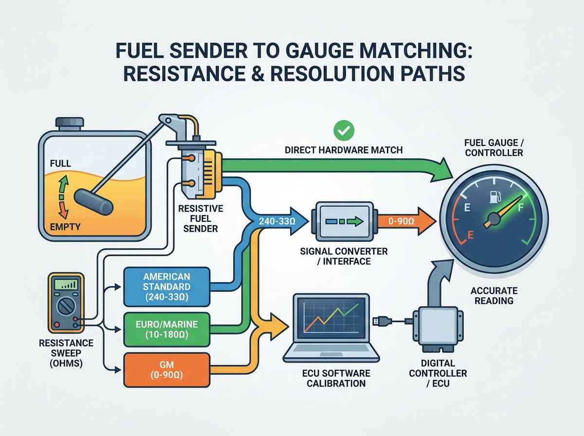
Standard American (Stewart Warner): 240 ohms (Empty) to 33 ohms (Full). Understanding 240-33 ohm fuel sender compatibility is critical for classic American muscle cars and aftermarket gauges.
European / Marine Standard: 10 ohms (Empty) to 180 ohms (Full). European automakers and many marine vessels utilize this low-to-high resistance sweep.
Asian / Aftermarket Standard: 0 ohms (Empty) to 190 ohms (Full). Choosing a 0-190 ohm fuel level sender is common in modern marine and custom applications.
Ford / Chrysler (Pre-1989): 73 ohms (Empty) to 10 ohms (Full). This high-to-low sweep is notorious for causing headaches during restomod builds.
GM (Pre-1965): 0 ohms (Empty) to 30 ohms (Full). Early General Motors vehicles relied on this very narrow resistance window.
GM (1965+): 0 ohms (Empty) to 90 ohms (Full). GM expanded the resistance range in the mid-1960s for better gauge resolution.
To help you visualize these differences quickly, we compiled the data below.
Standard Fuel Sender Resistance Ranges by Region and Manufacturer
Standard / Manufacturer
Resistance at Empty (Ohms)
Resistance at Full (Ohms)
Sweep Direction
Standard American (Stewart Warner)
240
33
High to Low
European / Marine
10
180
Low to High
Asian / Modern Aftermarket
0
190
Low to High
Ford / Chrysler (Pre-1989)
73
10
High to Low
GM (Pre-1965)
0
30
Low to High
GM (1965+)
0
90
Low to High
Notice how some systems sweep from high resistance to low resistance as fuel fills the tank. Others do the exact opposite. If you mix a high-to-low sender on a low-to-high gauge, your dashboard will tell you the tank is full when you are actually running on fumes.
Evaluation Framework: Choosing Your Resolution Path
When facing a mismatch, evaluate the three viable solution paths based on budget, labor, and system architecture. Every build carries unique constraints. A vintage restoration demands different problem-solving strategies than a modern race car build. We divide the solutions into three structured paths.
Path 1: Direct Component Replacement (Hardware Match)
The most straightforward method involves physically swapping hardware so both components share the identical resistance standard. You can either buy a new gauge tailored to your existing tank or buy a new sender tailored to your dashboard.
Pros: This provides the most reliable fix. You establish the lowest point of failure because you remove complex intermediary electronics. Analog systems inherently favor direct hardware matches.
Cons: It requires intense physical labor. You must drop the tank to swap the sender unit or modify the dash cluster to swap the gauge. Custom-fabricated tanks often lack universal mounting flanges, making physical sender swaps difficult.
Path 2: Inline Signal Converters / Interface Modules
If you cannot change the hardware, you can alter the signal mid-stream. An inline programmable signal converter sits between the tank and the dashboard. It intercepts the resistance signal, recalculates it, and outputs the exact resistance your gauge expects.
Pros: This allows you to keep original OEM gauges while running modern aftermarket fuel tanks. Programmable modules easily invert signals. For example, they can effortlessly convert a 240-33 ohm sender to drive a 0-90 ohm gauge.
Cons: It adds a potential electronic point of failure. These modules demand clean 12V power and highly secure grounding to function. Voltage spikes can occasionally corrupt their programming.
Path 3: ECU / Controller Software Calibration
Modern builds increasingly utilize standalone Engine Control Units (ECUs) or digital dash displays. These systems do not rely on fixed analog hardware calibrations. Instead, you define the parameters in the software interface.
Pros: You face zero hardware cost. This method proves ideal for EFI conversions running systems like Holley, Haltech, or HP Tuners. You simply type the Empty and Full values into a scaling table, and the computer handles the rest.
Cons: It strictly requires a digital dash or ECU setup capable of custom sensor scaling. Traditional analog gauges cannot benefit from this software-level manipulation.
Implementation Realities: Testing and Grounding Risks
Even perfectly matched components will fail if installed poorly. A faulty ground remains the single most common reason a compatible sender and gauge fail to operate correctly. A floating ground adds unintended resistance to the electrical circuit, artificially skewing the gauge reading toward the "high resistance" end of the sweep. If your needle jumps erratically when you hit a bump, you almost certainly suffer from a loose or corroded ground connection.
To prevent these frustrating electrical gremlins, you must follow a strict testing protocol before finalizing any installation. Bench testing verifies component health without crawling under a vehicle.
Testing Protocol:
Disconnect the sender wire completely from the gauge to isolate the circuit.
Set a digital multimeter to measure Ohms (Ω).
Place one multimeter probe on the sender output terminal. Place the other probe on a known, clean chassis ground.
Physically sweep the float arm slowly from the bottom position (Empty) to the top position (Full). If the unit is already installed, fill the tank incrementally using a measured jerry can to log the resistance curve manually.
Observe the multimeter screen. The resistance numbers should roll smoothly up or down. Any sudden jumps to zero (a dead short) or infinity (an open circuit) indicate a damaged resistor board.
Beyond electrical accuracy, you must prioritize mechanical safety. Fuel systems operate in environments saturated with highly flammable vapors. Ensure all connections at the fuel tank utilize sealed, spark-proof automotive connectors. Standard uninsulated crimp spades invite corrosion and pose severe fire risks. We highly recommend utilizing Weatherpack or Deutsch style connectors. These sealed units keep moisture out, guarantee strong terminal contact, and mitigate the risk of stray sparks near fuel vapor sources.
A common mistake during implementation involves relying on the fuel tank chassis straps for grounding. Rust and rubber isolators easily disrupt this path. Always run a dedicated ground wire directly from the sender flange to a clean, bare-metal point on the main vehicle chassis.
Shortlisting Logic: Next Steps for Your Build
Applying this knowledge requires looking at the current state of your project. The best path forward depends entirely on where you currently stand in your build process. Review these actionable next steps to finalize your system architecture.
If you have an uninstalled tank: Measure the sender resistance manually before installation. Use your multimeter to log the Empty and Full values while the unit sits on your workbench. Once you confirm these numbers, match your gauge purchase directly to this reading. Taking five minutes to measure a bare tank saves hours of diagnostic labor later.
If you are retaining a rare OEM gauge: Preserving a classic dashboard often means keeping original instruments. Instead of trying to find a perfectly matched classic sender unit, purchase an inline programmable signal converter. Modern aftermarket tanks use different resistance sweeps. A programmable module is significantly more cost-effective and reliable than attempting to custom-wind a mechanical sender rheostat to match a 60-year-old gauge.
If you are running a standalone ECU: Modern electronics offer ultimate flexibility. Purchase the most reliable, easily sourced sender available on the market today. Common sweeps like 0-90 or 240-33 remain incredibly easy to find. Install the robust hardware, boot up your tuning laptop, and map the voltage/ohm curve directly in the calibration software. This bypasses analog limitations completely and provides pinpoint accuracy.
Conclusion
Matching a fuel sender to a gauge is not a guessing game; it is a straightforward exercise in identifying resistance limits and sweep direction. By mapping your exact empty and full ohm values, you eliminate the guesswork that causes dead dashes and stranded vehicles.
You should prioritize direct hardware matching where feasible, keeping analog circuits as simple as possible. However, when preserving legacy dashboard hardware is strictly required, leverage reliable inline signal converters or ECU mapping tools to bridge the communication gap.
Always test your components on the bench with a digital multimeter before executing the final installation. Confirming smooth resistance sweeps outside the vehicle protects your time and budget. Finally, prioritize clean, dedicated chassis grounds and sealed electrical connectors to ensure your perfectly matched system remains accurate for years to come.
FAQ
Q: Can I use any fuel sender with my aftermarket gauge?
A: No. The sender’s resistance range (e.g., 240-33 ohms) must explicitly match the gauge's programmed range. Mismatches cause severe inaccuracies. If you cannot match the hardware directly, you must install an inline programmable converter to translate the signal.
Q: Why is my fuel gauge reading backwards?
A: You likely have a reversed sweep compatibility issue. For example, you might be using a 0-90 ohm gauge with a 90-0 ohm sender. This requires replacing one of the physical components or installing a reversing interface module to correct the output.
Q: How do I test if my resistive fuel level sender is broken?
A: Remove the sender and connect a multimeter set to Ohms across the signal and ground terminals. Slowly move the float arm. The resistance should change smoothly. If the reading drops to zero (short) or infinite (open circuit) mid-sweep, the internal board is damaged.
Q: Do I need a special sender for an EFI conversion?
A: Not necessarily. Most standalone ECUs can be calibrated via software to read any standard resistive sweep. As long as you know the exact Empty and Full ohm values of your existing unit, you can program the ECU to read it perfectly.
Top-rated designer and manufacturer of level-sensor and float-switch