Traditional analog resistive senders often fail in rough marine environments. Heavy vessel vibration, constant saltwater corrosion, and mechanical contact wear cause erratic dashboard readings. Boat operators frequently experience unexpected sensor breakdowns during offshore voyages.
Modern multi-function displays (MFDs) and digital switching systems demand continuous telemetry. Shifting to digital networks like NMEA 2000 or SAE J1939 ensures seamless communication across your fleet. Relying on outdated analog components creates dangerous blind spots in fuel management.
This guide provides a structured evaluation framework for specifying modern hardware. We will examine digital protocols, essential material requirements, and complex tank geometry calibration. You will learn how to choose the correct sensor without risking network incompatibility.
Key Takeaways
Protocol dictates compatibility: Ensure strict alignment between the sensor’s protocol (NMEA 2000 vs. J1939) and the vessel's core network.
Material selection is non-negotiable: Only specify SUS316 or 316L stainless steel to prevent saltwater corrosion and fuel degradation.
Damping matters: Look for sensors with algorithmic or mechanical anti-slosh capabilities to maintain stable readings in rough seas.
Tank geometry requires calibration: Stepped or V-shaped hull tanks require multipoint programmable sensors for true volumetric accuracy, not just linear depth.
Establishing Success Criteria for a Marine Fuel Level Sender
Upgrading your vessel requires a clear definition of success. A reliable marine fuel level sender must establish a flawless digital baseline. It should offer zero dead zones from the top to the bottom of the tank. The device must connect natively to your multi-function display. You should avoid installing fragile analog-to-digital converters. These intermediate gateways introduce unnecessary points of failure. True success means achieving long-term durability without ongoing maintenance.
You must actively avoid common failure modes associated with lower-tier components. Cheap senders often suffer from float sticking inside the shaft. They also exhibit poor resolution. You might see large, sudden jumps in fuel readings instead of smooth transitions. Galvanic corrosion destroys inferior metals rapidly in saltwater environments. Protecting your tank requires selecting materials designed specifically for marine exposure.
Evaluating hardware involves weighing upfront costs against long-term operational savings. Premium digital senders require a higher initial investment. However, they drastically reduce the operational cost of false low-fuel alarms. Sudden gauge drops disrupt commercial marine operations and ruin recreational trips. Investing in quality prevents premature hardware replacements. It keeps your vessel out of the repair yard and on the water.
Network Protocol Alignment: NMEA 2000 vs. J1939 Marine Tank Monitoring
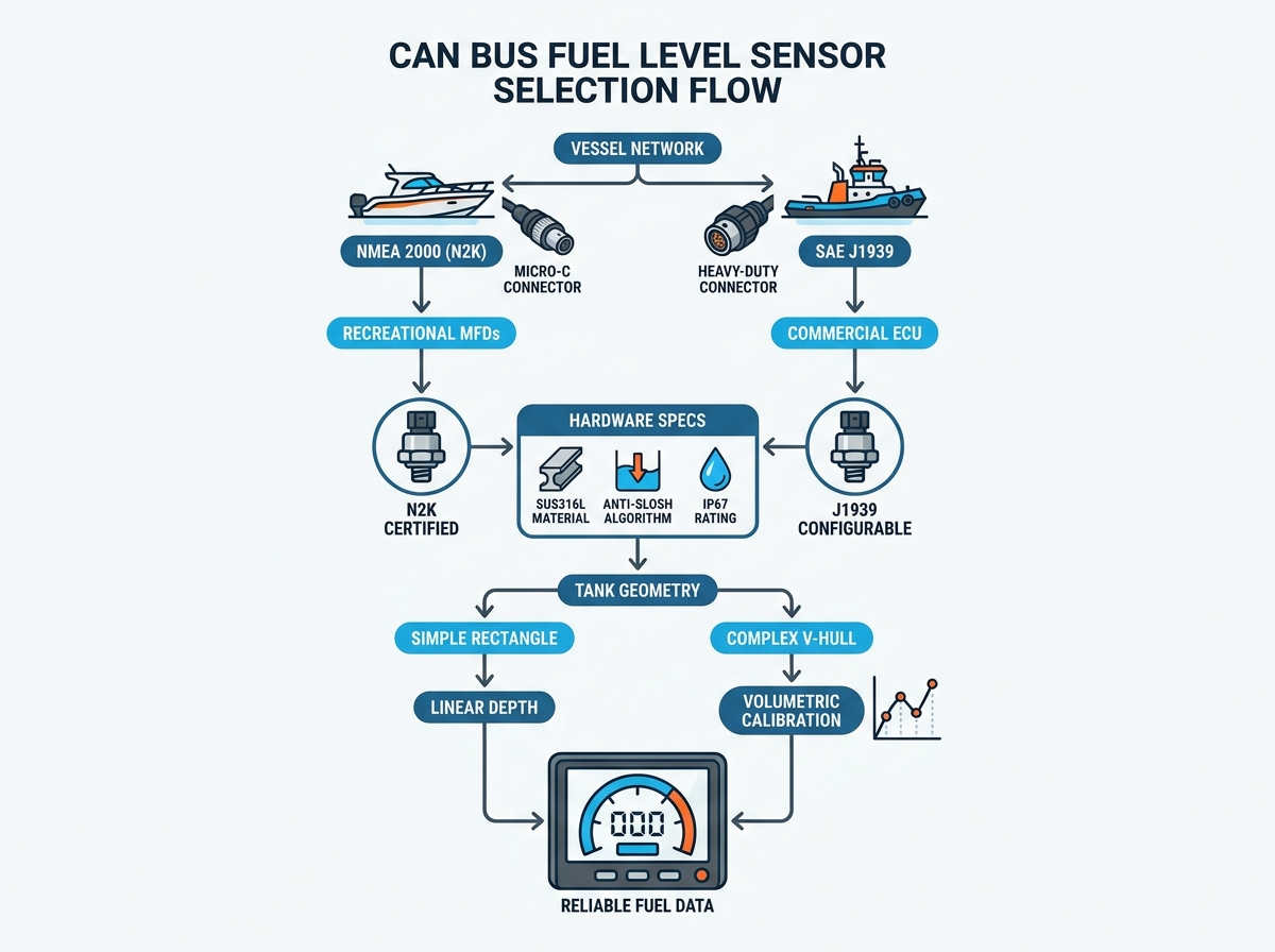
Selecting the right digital protocol prevents disastrous network collisions. The marine industry relies primarily on two standards. You must align your sensor choice with your existing backbone.
NMEA 2000 (N2K) Integration
NMEA 2000 dominates recreational and light commercial vessels. It uses a standardized messaging format over a Controller Area Network (CAN). It requires standard DeviceNet micro-C connectors. You can easily plug these into existing backbone tees.
Your primary evaluation criterion is official NMEA 2000 certification. Certified sensors ensure plug-and-play integration with major brands like Garmin, Raymarine, or Simrad. Uncertified knockoffs drop data packets. They often cause display freezing or network resets.
SAE J1939 Configuration
Heavy commercial marine operators, tugs, and diesel-heavy fleets prefer the SAE J1939 protocol. This standard communicates directly with heavy-duty engine Electronic Control Units (ECUs). It handles vast amounts of diagnostic data.
When implementing J1939 marine tank monitoring, you must evaluate source address configurability. The device needs baud rate matching capabilities. Most J1939 networks operate at 250 kbps. The sensor must hold its configuration during power cycles.
The Risks of Dual-Protocol Sensors
Some vendors offer cheap "dual-protocol" sensors claiming to support both NMEA 2000 and J1939 simultaneously. You should avoid these units. They often lack proper hardware isolation. They rarely feature certified communication stacks. Mixing standards on a single uncertified chip risks flooding the CAN bus with error frames.
Marine Network Protocol Comparison
Protocol Feature
NMEA 2000 (N2K)
SAE J1939
Target Vessels
Recreational, Light Commercial
Heavy Commercial, Tugs, Diesel Fleets
Connector Type
DeviceNet Micro-C (5-pin)
Deutsch, M12, or custom pigtails
Baud Rate
250 kbps
250 kbps (sometimes 500 kbps)
Integration Focus
Navigational MFDs (Garmin, Simrad)
Engine ECUs, Fleet Telematics
Hardware Evaluation: Specifications for Marine Environments
Marine environments destroy substandard hardware rapidly. A reliable CAN bus fuel level sensor must withstand continuous vibration, temperature swings, and corrosive chemicals.
Material Integrity Requirements
Material selection dictates the lifespan of the device. You must insist on SAE 316 or 316L stainless steel for the entire sensor body. Avoid 304 stainless steel. It lacks the molybdenum content necessary to resist saltwater pitting. Never use plastic sensor tubes for below-deck fuel applications. Plastics degrade quickly when exposed to modern ethanol blends or aggressive diesel additives.
Assessing Sensing Technology
You generally have two reliable sensing technologies to choose from for marine applications.
Reed Switch and Magnetic Float: This technology uses a series of internal magnetic switches. It is highly reliable. However, its accuracy depends on the density of the internal switches. You should aim for models offering a 10-21mm step resolution.
Capacitive Sensing: These are solid-state devices with no moving parts. They provide continuous, stepless resolution. However, they require strict dielectric calibration. Changes in fuel types (switching from standard diesel to biodiesel) can alter the dielectric constant and skew readings.
Anti-Slosh and Damping Profiles
Vessels experience constant pitch and roll. This movement causes fuel to slosh violently. Without damping, your gauge needle will swing erratically. Premium digital sensors utilize software-level signal damping. They average the readings over a few seconds before broadcasting the CAN message. Some models use mechanical baffle tubes around the float. You need at least one of these methods to ensure steady data.
Environmental Ingress Ratings
The topside of the sensor faces bilge water, condensation, and occasional washdowns. The sensor head and wiring harness must carry an IP67 rating as a strict minimum. IP68 ratings provide even better protection against continuous submersion.
Handling Complex Tank Geometry and Calibration
Boat builders rarely use perfectly rectangular fuel tanks. Hull contours dictate complex, irregular tank shapes. This geometric reality creates a massive problem for standard linear measurements.
The Linear Versus Volumetric Problem
Standard sensors measure the depth of the liquid. They provide a linear output based on height. A linear depth reading on a V-shaped hull tank completely misrepresents the actual remaining fuel volume. The top half of a V-tank holds significantly more fuel than the narrow bottom half. If a linear sensor reads 50% depth, the tank might only contain 25% of its total fuel volume. This discrepancy causes operators to overestimate their remaining range.
Programmable Multipoint Calibration
You solve this problem by selecting a programmable digital sensor. Advanced CAN bus models allow OEM or user-level custom profiling. You can input a 5-point or 10-point volume curve. The sensor software maps specific fluid heights to actual gallon or liter values. This converts a raw linear measurement into a precise volumetric output. Your MFD displays the true usable fuel.
Instance Configuration for Multi-Tank Vessels
Larger vessels utilize multiple fuel tanks. You might have Port, Starboard, and Center tanks. The CAN bus network needs to differentiate between these physical sources. The sensor must allow easy re-assignment of "Data Instances." By configuring the instance number, you prevent the MFD from confusing the Port tank data with the Starboard tank data. Look for sensors that offer simple instance programming tools or dip-switch configurations.
Implementation Realities and Installation Risks
Even the best hardware fails if installed improperly. Physical constraints and network topologies often dictate the success of your refit.
Flange and Mounting Standards
Your new sensor must match the physical cutout on your tank. Most marine tanks use the standard SAE 5-hole mounting pattern. Others utilize threaded ports. If your tank has threads, you must specify the correct thread pitch, such as a 1.25" BSP connection. Pay close attention to the sealing gasket. Standard rubber degrades in diesel. You must use NBR, FPM, or FKM (Viton) gaskets for strict chemical resistance.
Network Topology Constraints
CAN bus networks follow strict architectural rules. You cannot simply splice wires together. For NMEA 2000, drop cables connect the sensor to the main backbone. The maximum allowed length for a drop cable is 6 meters (about 20 feet). Exceeding this length degrades the data signal. Additionally, the main network backbone must have proper termination resistors at both ends. Missing terminators cause immediate communication failures.
Clearance and Baffle Interference
Many large marine tanks contain internal structural baffles. These metal plates prevent massive fuel shifts during turns. You must account for the physical footprint of the sensor float. Ensure the float mechanism will not strike or rub against internal tank baffles. A rubbing float eventually sticks. It causes permanent dead zones in your readings. Always inspect the tank interior with a flashlight before dropping the new unit in place.
Shortlisting Logic: How to Make the Final Decision
Navigating the specification process requires a methodical approach. Follow these strict steps to lock in the correct hardware for your vessel.
Audit the existing network: Identify your current MFD brand and model. Determine if you run an NMEA 2000 backbone or a J1939 architecture. Count the available open ports on your network tees.
Measure tank depth accurately: Insert a rigid measuring stick into the tank to find the exact internal depth. Order the sensor length 10 to 25mm shorter than this maximum depth. This gap prevents the sensor from bottoming out. It protects the unit from hull flexing and mechanical damage.
Conduct thorough vendor vetting: Do not buy blind. Demand technical datasheets from the manufacturer. Verify their official protocol certification numbers. Confirm the material composition is true 316L stainless steel. Review their warranty terms for marine deployments.
Next-Step Action: Gather your vessel's tank schematic diagrams. Document your current network architecture. Bring these specifications to your chosen suppliers before requesting formal quotes. This preparation prevents costly mismatches.
Conclusion
Selecting the right digital fuel telemetry equipment requires careful planning. It is an exercise in matching digital networking protocols with robust marine-grade metallurgy. Analog systems no longer meet the demands of modern digital vessel management.
Prioritize official network certification over unverified dual-protocol claims.
Insist on 316L stainless steel to outlast harsh saltwater environments.
Utilize multipoint calibration for accurate volumetric readings in V-hull tanks.
Size your hardware carefully to avoid internal baffle strikes and bottoming out.
Do not compromise on material durability for minor upfront cost savings. Reliable data keeps your engines running safely offshore.
FAQ
Q: Can I connect a CAN bus sensor directly to an analog gauge?
A: No. CAN bus sensors output digital data packets. Analog gauges require varying electrical resistance to move a physical needle. You must use a CAN-compatible digital display, an MFD, or install a dedicated digital-to-analog gateway to read the signal.
Q: How do I assign multiple sensors for port and starboard tanks?
A: You configure unique data instances for each sensor. Vendors provide PC-based configuration tools or allow adjustments directly through compatible MFDs. Assigning "Instance 0" to Port and "Instance 1" to Starboard keeps the data streams distinct.
Q: What happens if I use a J1939 sensor on an NMEA 2000 network?
A: The system will fail. The physical connectors do not match. More importantly, the software packet structures are incompatible. The MFD cannot decode the J1939 messages unless you install a specialized J1939-to-N2K protocol gateway.
Q: Are capacitive CAN bus sensors better than reed switch floats?
A: It depends on your application. Capacitive sensors offer continuous, stepless resolution without moving parts. However, they are sensitive to changes in fuel dielectric properties. Reed switch floats are mechanically robust and ignore fluid property changes, though they have stepped resolution.
Top-rated designer and manufacturer of level-sensor and float-switch