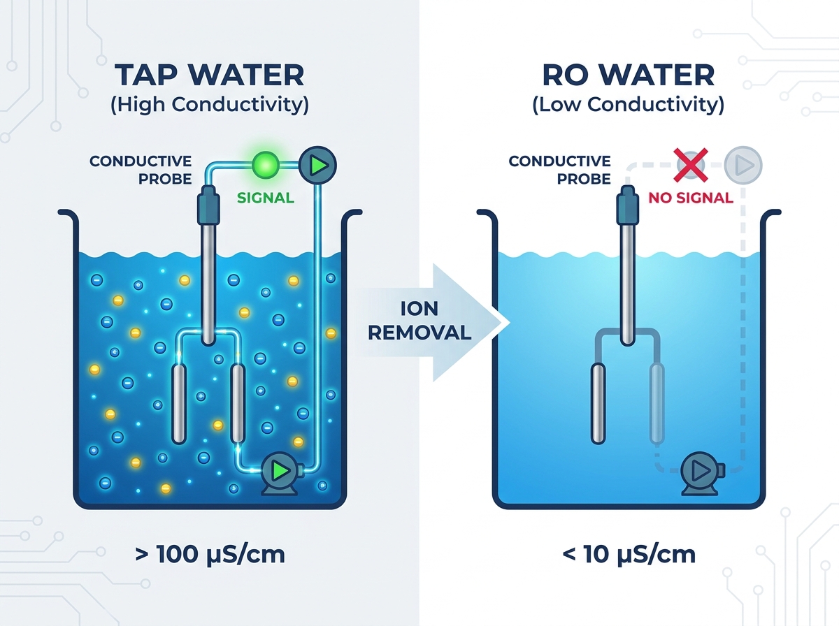
Specifying standard sensors for high-purity water systems presents a surprisingly common engineering pitfall. You might instinctively assume any basic switch will detect liquid in a holding tank. However, using a conductive water level probe in Reverse Osmosis (RO) water remains fundamentally flawed. This direct incompatibility stems from the underlying physics of liquid conductivity. Specifying the wrong sensor type leads to dangerous false readings across your facility. You risk severe pump dry-runs, overflowing tanks, and sudden unplanned downtime. When your sensors fail, your entire production process grinds to a halt. This article provides a strict technical evaluation of why conductive sensors fail in pure environments. We will outline the correct alternative technologies for reliable RO system integration. You will learn how to choose the right water tank level switch to protect your process infrastructure.
Key Takeaways
Physics limitation: RO water strips out the minerals and ions required to carry an electrical current, essentially acting as an insulator rather than a conductor.
Critical failure risks: Deploying conductive probes in RO tanks frequently results in false "tank empty" signals, leading to pump burnout or system lockouts.
Proven alternatives: Mechanical (PP float level switch) and non-contact (ultrasonic/optical) sensors are the industry standards for high-purity water applications.
Material matters: Selecting the right water level probe for RO water requires prioritizing chemical compatibility (e.g., Polypropylene or PTFE) to prevent leaching into the purified water.
1. The Core Problem: Why RO Water Defeats Conductivity
You must understand the mechanics of conductive sensors to see why they fail here. These devices operate on a very simple electrical principle. They rely entirely on the surrounding liquid to close an electrical circuit. The process works through these specific steps:
The connected controller applies a low alternating voltage to a primary metal electrode.
The liquid level rises and physically touches both the primary and ground electrodes.
Free-floating ions inside the liquid carry the electrical current across the gap.
The circuit completes, and the controller registers the presence of liquid.
This sequence relies heavily on ion density. The reverse osmosis process actively removes up to 99% of Total Dissolved Solids (TDS). The membrane strips out calcium, magnesium, sodium, and various natural salts. These specific elements provide the free ions needed to carry any electrical current. Without them, the water essentially becomes an electrical insulator.
We can observe this severe ion deficit by comparing liquid conductivity thresholds. Standard tap water usually measures between 100 and 500 microSiemens per centimeter (µS/cm). This high measurement guarantees reliable circuit closure. In stark contrast, pure RO water routinely drops below 10 µS/cm. If you manage a Type II or Type III pure water system, the measurement often falls below 1 µS/cm. This creates an environment completely hostile to standard probes.
Table 1: Conductivity Versus Resistivity Threshold Data
Water Type
Typical Conductivity (µS/cm)
Conductive Sensor Reliability
Municipal Tap Water
100 – 500 µS/cm
Excellent / Highly Reliable
Standard RO Water
1 – 10 µS/cm
High Failure Rate / Unpredictable
Ultra-Pure Water (Type II/III)
< 1 µS/cm
Complete Failure / Insulator
Many technicians attempt a dangerous workaround to solve this issue. They maximize the controller sensitivity dial to read ultra-low conductivity. We refer to this as the "sensitivity hack" fallacy. Cranking up the sensitivity creates highly erratic switching behavior. The system starts reacting to ambient humidity inside the tank headspace. It triggers repeatedly from minor surface splashing. Surface condensation easily tricks the sensitive relays. You no longer measure actual liquid volume. You merely measure ambient dampness. This poor practice guarantees unpredictable system behavior over time.
2. Operational Risks of Using the Wrong Sensor in RO Systems
Deploying the wrong sensor quickly escalates into severe mechanical consequences. False negative readings represent a massive financial hazard for facility managers. If the pure water cannot complete the electrical circuit, the system reads empty. The controller assumes no fluid exists inside the vessel. It then commands delivery pumps to activate without adequate fluid supply. This specific failure causes destructive pump dry-running.
High-pressure RO delivery pumps rely heavily on passing fluid for internal cooling. They also need this fluid for mechanical lubrication. Running these expensive pumps dry causes extreme internal cavitation. The internal impellers warp rapidly. Motor seals burn out from extreme frictional heat. You ultimately face substantial replacement costs and extended facility downtime.
False positive readings create equally destructive scenarios on the production floor. Condensation routinely pools between the metal electrodes inside enclosed vessels. If you utilize highly sensitive controllers, this single droplet bridges the gap. The controller instantly interprets this tiny droplet as a full tank. It quickly signals the intake valves to close prematurely. Conversely, minor surface splashing can trick the system into overfilling the vessel. The controller ignores the actual volume and commands continuous filling. This creates dangerous flooding hazards across your facility floors. You also waste thousands of gallons of expensive purified water.
Compliance and quality control suffer immensely under these conditions. Many modern industries rely on strict, unbroken batch integrity. Pharmaceutical plants demand absolute process control. Food and beverage facilities operate under tight safety regulations. Laboratory settings require exact dilution volumes. Erratic level sensing compromises every single batch you produce. An unreliable sensor violates standard operating procedures constantly. You risk complete batch rejection. Regulatory bodies often issue severe penalties for these specific process failures.
3. Evaluating Alternatives: The Right Water Level Probe for RO Water
You must select technologies completely immune to electrical conductivity changes. We heavily recommend integrating proven, physics-based alternatives. Finding the correct water level probe for RO water ensures long-term operational stability.
Mechanical solutions currently offer incredible reliability for pure environments. The PP float level switch serves as the primary industry standard today. These Polypropylene magnetic float switches provide a highly effective replacement strategy. They bypass the conductivity problem by relying entirely on physical buoyancy. A durable magnetic float simply rises alongside the liquid surface. It then triggers an internal hermetically sealed reed switch.
Pros: They boast exceptionally high reliability and very low implementation cost. They remain entirely immune to any water purity fluctuations.
Cons: They carry a microscopic risk of mineral scaling over time. However, severe scaling remains exceptionally rare in correctly filtered RO water.
Non-contact sensing provides another excellent, highly precise alternative. Ultrasonic and radar sensors excel in highly regulated, sanitary applications. Sanitary environments demand minimal physical contact whenever possible. You rarely want external parts touching your purified product. Non-contact sensors bounce sound waves or radar pulses off the liquid surface. They calculate precise volume distances based on the return echo time.
You must evaluate these non-contact sensors against your specific facility criteria. They require a noticeably higher initial capital expenditure. They also demand a clear, clean line-of-sight to the water surface below. Any internal tank obstructions will scatter the acoustic signal. However, they offer continuous 4-20mA monitoring. This gives you exact, real-time volume data rather than simple point-level switching.
Optical level sensors work flawlessly for specialized, small-scale configurations. They use precise infrared light refraction to detect liquid presence. A tiny glass or polysulfone prism sits at the sensor tip. When liquid covers this prism, the internal light beam bends away from the receiver. This absence of light triggers an immediate state change. Optical sensors remain ideal for small-scale pure water tanks. They also perform incredibly well as leak detection boundaries inside secondary containment trays.
4. How to Spec a Water Tank Level Switch for High-Purity Applications
Selecting the right hardware goes far beyond just the internal sensing mechanism. You must carefully evaluate material compatibility before final installation. Industry professionals frequently call RO water "hungry water" for a good reason. The advanced purification process strips out all natural trace minerals. The resulting water aggressively seeks to pull ions back into itself. It will rapidly leach metals from poorly specified mechanical components.
You must strictly avoid standard brass fittings in these pure environments. Never use low-grade stainless steel inside an active RO tank. Instead, prioritize highly inert materials for all wetted parts. We strongly recommend specifying Polypropylene (PP) or PTFE (Teflon) housings. If your pressure ratings demand metal, only select certified 316L Stainless Steel. These superior materials resist aggressive leaching and maintain your strict water purity.
Mounting configurations also dictate your ultimate sensor choice. You must evaluate top-mount versus side-mount installations carefully. Review your specific tank geometry and surrounding maintenance access points. Top-mount sensors work best for deep, extremely narrow holding tanks. They keep delicate wiring safely away from potential side impacts. Side-mount switches fit perfectly in shallow or restricted-height tanks. They also allow for easier routine maintenance access. Technicians can service them without removing heavy, cumbersome tank lids.
Electrical load considerations remain equally vital during the specification phase. You must differentiate between switching a low-voltage PLC input and directly switching a pump motor. A standard reed switch inside a plastic float easily handles a 24V DC PLC signal. It uses mere milliamps of current. However, it will instantly melt if you try to switch a 120V AC pump motor directly. Heavy inductive loads always require an intermediate relay or mechanical contactor. Always match your exact switch ratings to your facility's actual electrical demands.
5. Implementation Realities and Rollout Lessons
Even the highest-quality sensors fail if installed incorrectly. Managing active liquid turbulence represents your first major rollout hurdle. Float switches and optical sensors can bounce wildly in turbulent fill zones. Rapid water movement causes the sensor relay to toggle on and off rapidly. This frantic toggling damages your heavy pumps and confuses your logic controllers. We highly recommend installing custom stilling wells. A stilling well is simply a slotted PVC pipe surrounding the sensor body. It calms the water surface immediately around the delicate probe.
You can also solve turbulence issues through software modifications. Consider utilizing PLC debounce timers in your logic controller. A debounce timer forces the controller to wait a few seconds before acknowledging a physical state change. It ignores rapid, temporary signal bounces. This simple programming addition effectively prevents rapid mechanical relay cycling.
Redundancy best practices separate amateur setups from professional engineering deployments. Critical infrastructure always requires mechanical fail-safes. We strongly advocate for a robust dual-technology approach. Relying on a single point of failure invites eventual disaster. Install a continuous ultrasonic monitor for your primary level control operations. Then, install a hardwired mechanical float switch slightly above your normal fill line. This secondary mechanical float acts as the ultimate high-level emergency shutoff. If the primary ultrasonic sensor fails completely, the float prevents a catastrophic facility overflow.
Maintenance expectations must remain highly realistic despite the clean environment. Pure water naturally keeps internal tanks relatively clean over time. However, you still need a formalized, strict inspection schedule. Technicians must check mechanical floats for physical binding every six months. Inspect all external wiring jackets for chemical degradation or temperature cracking. You must also verify your emergency high-level switches manually. Trigger them by hand to ensure the alarms actually sound. Preventive maintenance costs mere pennies compared to a flooded production facility.
Conclusion
Conductive probes and purified RO water remain fundamentally incompatible. The reverse osmosis process actively removes the vital ions necessary for electrical conductivity. Attempting to force these standard sensors to work introduces unacceptable operational risk. Utilizing the "sensitivity hack" only leads to false readings, ruined pumps, and flooded production floors.
You must prioritize physics-compatible solutions for your facility. We strongly advise engineers and facility managers to audit their current RO storage tanks immediately. Identify and replace any failing conductive probes before they cause critical system downtime. Upgrade your infrastructure with a reliable mechanical float or advanced ultrasonic sensor. Match these new devices specifically to your required purity levels and operational budget. Taking proactive steps today guarantees long-term process safety and operational efficiency.
FAQ
Q: What is the minimum conductivity required for a standard conductive level probe?
A: Most standard conductive relays require a minimum of 10 to 50 µS/cm to function reliably. This baseline ensures the electrical circuit can close across the liquid gap. Reverse osmosis water typically falls well below this threshold, often measuring under 1 µS/cm, making standard conductive probes useless.
Q: Can I just increase the sensitivity on my conductive probe controller for RO water?
A: While some high-sensitivity controllers exist, pushing sensitivity to the maximum creates severe instability. The system becomes highly susceptible to false triggers from rising steam, tank condensation, or minor probe fouling. It is not a reliable long-term solution for industrial environments.
Q: Why is a PP float level switch preferred for RO water tanks?
A: Polypropylene (PP) is highly chemically inert. It will not leach unwanted contaminants or trace metals into the purified, "hungry" RO water. Furthermore, its mechanical operation relies strictly on liquid buoyancy. This makes it completely immune to the water's total lack of electrical conductivity.
Q: Will a capacitive sensor work in reverse osmosis water?
A: Yes, capacitive sensors can successfully detect RO water through non-metallic tank walls. They rely on dielectric changes rather than direct electrical conductivity. However, they require highly careful calibration upon installation. They can also be negatively affected by severe changes in ambient temperature or heavy exterior tank condensation.
Top-rated designer and manufacturer of level-sensor and float-switch