Reliable tank monitoring depends not only on the sensor itself but also on how it is installed and calibrated. A water level probe sensor can deliver highly stable detection for tanks, reservoirs, and industrial equipment, yet poor installation practices or incorrect calibration can lead to inaccurate signals, pump failures, or unexpected alarms. Many field issues that appear to be sensor defects are actually caused by mounting position errors, wiring problems, or poorly defined reference points. Understanding how to install water level probe sensors correctly and how to calibrate them properly ensures that the system delivers consistent performance. This practical guide explains the key preparation steps, installation procedures, calibration methods, and testing practices that help transform a simple sensor into a reliable control point within a tank monitoring system.
What to check before installation starts
Confirm the tank dimensions and usable measuring range
Before installing a sensor, the physical characteristics of the tank must be clearly understood. Tank height determines the probe length required for the detection point. Some tanks require detection only at a high level or low level, while others require multiple control points.
Accurate measurement of tank depth and usable liquid range helps ensure the sensor is placed at the correct level. If the probe is too short, it may never reach the detection zone. If it is too long, it may interfere with the bottom of the tank or internal structures.
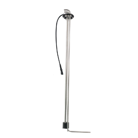
Bluefin Sensor Technologies Limited provides customizable probe lengths so the sensor can match the exact tank dimensions used in water storage systems, industrial coolant tanks, or process equipment.
Identify the liquid conditions, including foam, sediment, and turbulence
Liquid characteristics play a significant role in sensor performance. Water tanks may contain foam, sediment, or suspended particles depending on the source of the liquid and the operating environment.
Foam layers can create false signals if the sensor is placed too close to the surface where turbulence occurs. Sediment buildup at the bottom of the tank can also interfere with detection if the probe is installed too low.
Understanding the behavior of the liquid helps determine the safest and most stable sensing point inside the tank.
Match the sensor output to the receiving device or controller
Before installation begins, it is also important to confirm the signal interface used by the monitoring system. The output from the sensor must be compatible with the receiving equipment, whether that is a controller, alarm unit, or pump automation system.
Some applications use simple switch outputs for high or low level detection. Others may require signals compatible with control panels or monitoring systems.
Ensuring signal compatibility during planning avoids wiring modifications and prevents communication issues after installation.
How to choose the right mounting position
Why bottom contact, sidewall interference, and turbulence create false readings
The mounting position of a sensor determines how accurately it can detect the liquid level. If the probe touches the tank bottom, it may become blocked by sediment or debris. Sidewall interference can also affect sensor response if the probe is placed too close to the tank structure.
Liquid turbulence caused by pumps or inflow pipes can temporarily raise or lower the local level around the sensor. When the probe is installed in these unstable areas, it may generate fluctuating signals.
Selecting a location away from direct liquid movement improves reliability.
How much clearance to leave from sludge or debris zones
Most tanks accumulate some form of residue or sludge near the bottom. For this reason, sensors used for low-level detection should be placed slightly above the base of the tank.
Maintaining sufficient clearance helps prevent buildup from interfering with the probe. It also allows the sensor to detect the actual liquid level instead of reacting to sediment deposits.
When vertical mounting is preferable
Vertical mounting is commonly used because it allows the probe to extend directly into the liquid and remain stable during operation. This orientation reduces the likelihood of contact with tank walls or internal structures.
Vertical installation also simplifies maintenance because the sensor can often be removed from the top of the tank for inspection or cleaning.
Step-by-step installation process
Prepare the mounting port, flange, or threaded entry
Installation begins with preparing the tank opening where the sensor will be mounted. The opening must match the thread or flange type used by the probe sensor.
The sealing surface should be clean and free of debris to ensure a leak-free connection. Proper sealing materials help protect the tank and maintain system safety.
Secure the probe and protect the cable route
After the mounting port is prepared, the probe can be inserted carefully into the tank. The sensor should be tightened according to the specified torque so that it remains stable during operation.
Cable routing is another important aspect of installation. The cable should be protected from mechanical damage and positioned away from areas where it may be exposed to excessive heat or vibration.
Proper cable management improves long-term reliability.
Check sealing, connector fit, and mechanical stability
Once the probe is secured, the installer should verify that all sealing elements are properly positioned and that connectors are firmly attached.
The sensor should remain stable without excessive movement. Mechanical stability ensures that the probe remains aligned with the intended detection point during operation.

Wiring basics that affect signal quality
Power, ground, and output wiring essentials
Correct wiring is essential for accurate sensor performance. The power supply, ground connection, and signal output must all be connected according to the sensor specifications.
Improper wiring can prevent the sensor from transmitting reliable signals or may cause intermittent detection issues.
Avoiding loose terminals and electrical noise
Loose electrical terminals can cause unstable signals that appear similar to calibration errors. Electrical noise from nearby equipment can also interfere with sensor signals if wiring is not properly shielded.
Maintaining secure connections and appropriate cable routing helps prevent these issues.
Why the wrong wiring can look like a calibration problem
When signal wiring is incorrect, the system may show delayed responses or unexpected switching behavior. These symptoms are often mistaken for calibration problems.
In many cases, verifying the wiring connections resolves the issue without additional adjustments.
How to calibrate a water level probe sensor correctly
Set the empty reference point
Calibration begins by defining the lowest reference point of the tank. This point represents the condition where the tank is empty or at the minimum operational level.
Setting this reference allows the control system to understand when the tank has reached a critical low level.
Set the full or target operating point
The next step is to define the full level or operational limit of the tank. This is the point where pumps should stop or alarms should activate to prevent overflow.
Correctly setting this threshold ensures stable tank operation and protects equipment.
Verify switching thresholds or output response
Once the reference points are defined, the installer should verify that the sensor responds at the correct liquid levels.
Testing the switching thresholds ensures that the sensor interacts properly with the control system.
How to test the sensor after installation
Simulate rising and falling levels
Testing should simulate both increasing and decreasing liquid levels. This can be done during tank filling or by controlled water addition during system startup.
Observing sensor behavior during these conditions confirms that the detection point is accurate.
Compare sensor response with actual tank conditions
The installer should compare the sensor output with the visible liquid level inside the tank. This comparison ensures that the sensor response matches the actual condition.
If discrepancies appear, minor adjustments to the installation height or calibration settings may be required.
Record settings for future maintenance and replacement
Documenting the final settings is an important step that is often overlooked. Recording probe length, mounting height, and switching thresholds makes future maintenance easier.
If the sensor ever needs replacement, these records allow technicians to reproduce the same configuration quickly.
Common installation and calibration mistakes
Even experienced installers sometimes encounter issues during sensor installation. Understanding the most common mistakes helps prevent unnecessary troubleshooting.
Mistake | What the user may notice | Likely cause | Recommended fix |
Probe installed too close to tank bottom | Frequent false low-level signals | Sediment interference | Raise installation height |
Sensor located near inlet pipe | Fluctuating signals | Liquid turbulence | Move probe to calmer area |
Incorrect wiring | No signal or unstable output | Misconnected terminals | Verify wiring diagram |
Calibration performed once only | Incorrect switching during operation | Conditions changed after installation | Re-test and validate under real conditions |
Conclusion
Correct installation and calibration determine whether a tank monitoring system operates reliably or produces unstable signals. A properly installed liquid level probe sensor provides dependable detection that protects pumps, maintains stable tank levels, and supports automated control systems. When tank dimensions, mounting position, and signal requirements are clearly defined, the sensor can be configured to match the application precisely. Bluefin Sensor Technologies Limited designs and manufactures stainless steel probe sensors and float switch solutions for tank monitoring and automation systems. If you are planning a new installation or upgrading an existing tank control system, contact us to discuss your application and find a suitable sensor configuration.
FAQ
1. How long does it take to install a water level probe sensor?
Installation time depends on tank access and wiring complexity, but most installations can be completed within a short period when the mounting port and wiring connections are prepared.
2. Can a water level probe sensor be installed in tanks with sediment?
Yes, but the probe should be installed slightly above the sediment layer to avoid interference with detection.
3. Why does my water level probe sensor give unstable signals?
Unstable signals may result from turbulence near the sensor, incorrect wiring, or installation in a location affected by foam or debris.
4. How often should calibration be checked?
Calibration should be verified periodically, especially after maintenance work, system upgrades, or changes in operating conditions.


