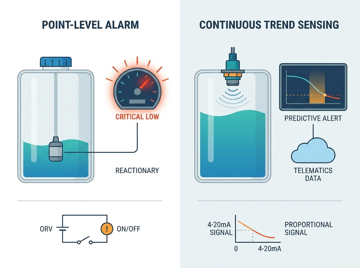
Catastrophic engine failure in heavy mobile equipment frequently traces back to undetected coolant loss. Relying solely on temperature gauges provides a delayed, reactionary metric. By the time the engine actually overheats, permanent damage is often already done. Protecting high-value assets requires proactive fluid level detection right at the reservoir.
Fleet managers and OEMs face a critical decision point. They must decide between two primary architectures to safeguard their machines. Discrete point-level alarms act as a final fail-safe during severe leaks. Alternatively, continuous level sensing provides real-time trend data for advanced diagnostics. Both methods offer distinct advantages.
Our goal is to objectively compare these two strategies. We will analyze implementation realities, integration complexity, and operational risks. This guide helps you specify the correct sensor architecture for your specific equipment.
Key Takeaways
A discrete coolant reservoir level switch is highly reliable and cost-effective for emergency shutdown protocols but lacks predictive insight.
Continuous sensing enables predictive maintenance by identifying slow coolant leaks over time, though it requires heavier ECU integration.
Mobile equipment applications demand specific sensor features—such as slosh delay, vibration immunity, and glycol resistance—regardless of the sensing method chosen.
Over-specifying a sensor increases integration complexity and costs; under-specifying risks false alarms and catastrophic equipment damage.
The Role of a Coolant Reservoir Level Switch in Mobile Equipment
Heavy machinery operates in brutal conditions. Unlike stationary tanks, mobile equipment coolant tank monitoring must account for extreme dynamic forces. Sensors endure constant chassis vibration, severe thermal shock from engine bay heat, and aggressive fluid sloshing across uneven terrain.
The cost of failure remains extremely high. A missed low-level event leads directly to engine seizure. Conversely, false positives cause immense frustration. If fluid sloshing triggers a false alarm, operators experience unnecessary downtime. Repeated false alarms cause operators to lose trust in the system entirely.
A sensor serves one fundamental purpose. It must provide a verifiable mechanical or electronic translation of fluid presence. It sends this data to the vehicle’s Engine Control Unit (ECU), telematics system, or dashboard indicator before thermal breakdown ever occurs. Fast, accurate detection saves engines.
Common Causes of Coolant Loss in Heavy Machinery
Punctured radiator cores from worksite debris.
Degraded rubber hoses failing under high pressure.
Loose clamps vibrating off during rough transit.
Internal block leaks escaping into the oil system.
Strategy 1: Low Coolant Level Alarm Sensors
Point-level sensors represent the industry standard for basic asset protection. They focus on identifying a single, critical fluid threshold.
Mechanism of Action
This strategy utilizes a magnetic float, an optical prism, or a capacitive probe. These devices trigger a simple on or off state when the fluid drops below a specified line. Float switches use a magnet to close a reed circuit. Optical sensors detect changes in light refraction when exposed to air. Capacitive probes sense the dielectric shift between liquid and air.
Primary Use Case
Operators rely on these devices for emergency indication. When a massive leak occurs, the sensor instantly triggers automated engine shutdown sequences. This prevents the block from melting down.
Operational Advantages
Simplicity & Reliability: These devices require minimal wiring. They integrate directly into existing dashboard lights or simple relay circuits. You do not need complex software to read a basic on/off signal.
Lower Upfront Cost: Point-level sensors are highly economical. They fit perfectly into standard OEM builds and large-scale fleet retrofits. A basic low coolant level alarm sensor provides massive ROI by saving a fifty-thousand-dollar engine.
Operational Limitations
The primary drawback is reactionary data. The system only alerts operators when the situation becomes critical. It cannot track fluid consumption rates. It will never identify a slow pinhole leak until the fluid breaches the critical threshold.
Strategy 2: Continuous Level Transmitters
Modern fleets increasingly demand granular data. Continuous transmitters provide a dynamic view of fluid volume at all times.
Mechanism of Action
These devices employ ultrasonic, hydrostatic, or continuous capacitive technologies. They output a proportional analog or digital signal. Common outputs include 4-20mA, 0-5V, or CAN bus (such as SAE J1939). As the fluid moves, the signal scales proportionally to represent exact volume.
Primary Use Case
Continuous monitoring suits advanced telematics programs and highly critical mobile assets. Mining haul trucks, large excavators, and industrial mobile generators frequently utilize this technology. The capital value of these machines justifies advanced telemetry.
Operational Advantages
Predictive Capability: Maintenance teams can monitor the slow degradation of coolant levels over several weeks. They schedule repairs during planned downtime before an emergency alarm ever sounds.
Granular Insight: Fleet managers view exact percentage levels on digital dashboards. Operators know exactly how much fluid remains before starting a long shift.
Operational Limitations
Implementation Complexity: Proportional data requires higher-tier ECU programming. Engineers must map analog-to-digital conversions accurately. They also must write sophisticated software filtering to manage dynamic fluid levels during machine movement.
Higher Component Expense: The initial procurement and long-term replacement costs are noticeably higher. Complex electronic transmitters cost significantly more than simple mechanical floats.
Key Evaluation Criteria: Alarm vs. Continuous for Your Fleet
Choosing the right architecture requires balancing risk, infrastructure, and organizational maturity. Not every machine needs advanced telemetry.
Asset Value vs. Sensor Cost (Risk Profiling)
You must evaluate if continuous monitoring justifies the asset protection. A standard utility tractor or small skid steer usually requires a simple discrete coolant reservoir level switch. Conversely, a multi-million-dollar mining excavator warrants continuous telematics to prevent expensive operational halts.
ECU and Telematics Infrastructure
Assess your current system capabilities. Can your vehicle's control unit process CAN bus or analog inputs? Many older or simpler machines only accept discrete digital inputs. Forcing a continuous sensor into an analog-deficient ECU requires expensive external converters.
Slosh Mitigation Requirements
Mobile equipment experiences violent movement. Continuous sensors read every ripple in the tank. They require aggressive software dampening to smooth out the data during transit. Point-level switches handle slosh much easier. They use mechanical slosh shields or built-in time delay relays to ignore temporary fluid drops.
Maintenance Culture
Continuous data offers zero value if nobody analyzes it. You only benefit if your organization maintains the infrastructure to monitor trends. If mechanics only react to red dashboard lights, stick to point-level alarms.
Comparison Summary: Point-Level vs. Continuous
Feature
Point-Level Alarm Switch
Continuous Level Transmitter
Data Output
Discrete (On/Off)
Proportional (CAN, 4-20mA)
Integration
Simple relays, basic ECU
Advanced ECU mapping needed
Leak Detection
Reactionary (Critical low only)
Predictive (Slow leaks visible)
Slosh Handling
Mechanical shields, time relays
Software filtering/dampening
Ideal Application
Utility vehicles, standard fleets
Mining trucks, critical assets
Implementation Risks and Installation Realities
Specifying the correct sensor is only half the battle. Poor installation ruins even the most robust devices.
Mounting Orientation and Location
Sensors must sit in a location representing true liquid level. Avoid areas of the reservoir prone to trapped air pockets. Keep the sensor away from extreme turbulence near return hoses. Dead zones in complex tank geometries trap stagnant fluid, causing false readings.
Material Compatibility
Ensure all wetted parts resist chemical attack. Housings, seals, and floats must withstand ethylene glycol, propylene glycol, and high-temperature corrosion inhibitors. Brass, stainless steel, and engineered plastics like Polysulfone or PPS serve as the industry standard. Using cheap plastics leads to rapid embrittlement.
Vibration and Wiring Integrity
The point of failure is often the connector, not the sensor itself. Specify heavy-duty, sealed connectors for all engine bay applications. The Deutsch DT series provides excellent moisture and vibration resistance. Ensure proper cable strain relief to survive aggressive mobile equipment vibration profiles.
Fail-Safe Circuit Design
Always wire point-level switches in a normally closed state. If a rock severs the wire, or the sensor loses power, the circuit opens. This triggers an immediate fault condition on the dashboard. If you wire it normally open, a severed cable masks a low-coolant event completely. You will never know the sensor failed until the engine seizes.
Best Practices for Heavy Duty Installation
Apply anti-seize or thread sealant compatible with glycol mixtures.
Route wiring harnesses away from exhaust manifolds and high-heat zones.
Install physical guards around external sensor housings to deflect flying rocks.
Test the system manually by draining the tank during commissioning.
Conclusion
The choice between point-level alarms and continuous sensing hinges on your system processing capabilities. You must weigh the critical nature of the asset against your current maintenance strategy. Simple applications thrive on simple solutions. Complex operations demand granular data.
We recommend defaulting to a robust, time-delayed alarm switch for reliable, cost-effective equipment protection. Upgrade to continuous sensing only if your telematics infrastructure actively utilizes predictive fluid trending. Otherwise, you pay for data you never use.
Review your vehicle's specific ECU input parameters today. Consult with a specialized sensor engineering team to evaluate pilot testing for your specific reservoir geometry. Taking proactive steps now prevents catastrophic breakdowns tomorrow.
FAQ
Q: Can a standard water level switch be used in a coolant reservoir?
A: No. Coolant relies on glycol mixtures operating at much higher temperatures. It possesses different specific gravities and chemical properties than pure water. Using a standard water switch risks rapid seal degradation, plastic embrittlement, and premature failure inside the hot engine bay.
Q: How do you prevent false alarms caused by vehicle movement?
A: False alarms are mitigated mechanically by using slosh shields around the sensor probe. You can also prevent them electronically by integrating a time-delay relay. This requires the sensor to read a low state for several continuous seconds before it triggers the dashboard alarm.
Q: What is the typical lifespan of a coolant reservoir level switch in heavy machinery?
A: With proper material selection and vibration-resistant wiring, industrial-grade switches typically last the lifecycle of the reservoir itself. Sensors lacking moving parts or utilizing heavily shielded floats easily survive five to ten years in aggressive mobile environments.
Top-rated designer and manufacturer of level-sensor and float-switch