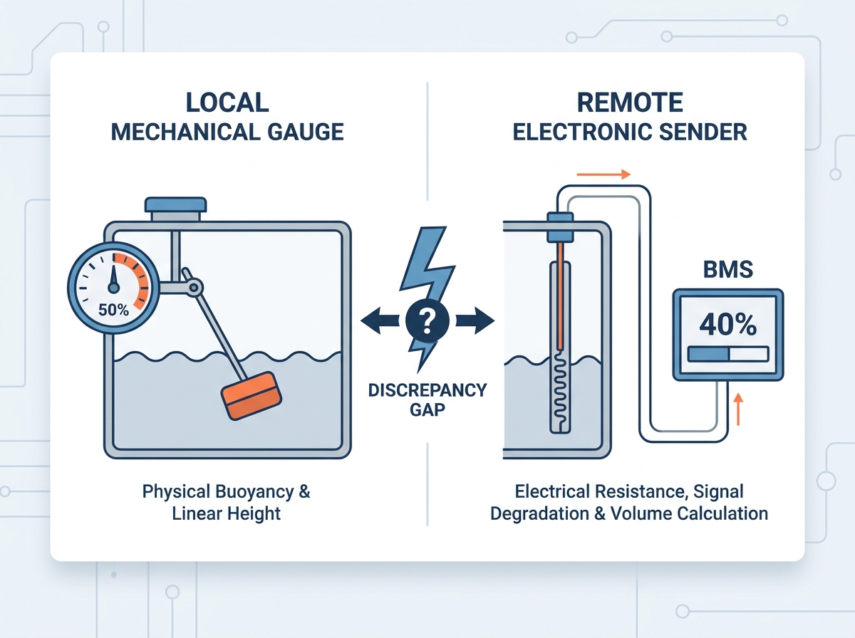
Facility managers overseeing mission-critical operations face a harsh reality. Discovering a discrepancy between the local tank gauge and the remote Building Management System (BMS) introduces unacceptable operational risk. We cannot rely on guesswork when backup power is on the line. The core issue lies in fundamental measurement methodology. Local and remote systems rarely measure the exact same physical property in identical ways. When local and remote fuel level readings differ, you risk dry-running generators during outages. Conversely, operators might cause environmental spills through accidental overfilling. Our purpose here is to decode these frustrating technical discrepancies. We will thoroughly evaluate modern telemetry solutions suitable for complex facilities. Finally, we provide a structured framework to standardize fuel level accuracy. You will learn how to unify critical data across your entire infrastructure.
Key Takeaways
Discrepancies usually stem from comparing two different measurement technologies (e.g., physical buoyancy vs. electrical resistance).
Irregular tank geometries require non-linear calibration that local analog dials cannot natively compute.
Upgrading to digital, continuous-level sensors mitigates signal degradation and provides a single source of truth for both local and remote displays.
Proper sensor selection requires evaluating tank depth, fluid type, and BMS integration protocols.
The Engineering Reality Behind Discrepant Fuel Readings
Business Problem Framing
Modern infrastructure relies heavily on uninterrupted backup power. Data centers, hospitals, and telecommunications hubs require absolute certainty regarding fuel reserves. Mismatched fuel data directly threatens this certainty. If a local gauge reads higher than the remote system, operators face dangerous ambiguity. Trusting the wrong number leads to disastrous consequences. You might dry-run a mission-critical generator during an active grid outage. Alternatively, you might order an unnecessary fuel delivery. Pumping new fuel into a tank you mistakenly believe is empty causes rapid overfilling. This results in severe environmental spills, heavy regulatory fines, and facility downtime.
The Core Conflict
When telemetry outputs clash, operators often assume one sensor is simply broken. In reality, the conflict usually stems from mismatched methodologies. A mechanical dial and an electronic sensor interpret the world differently. They translate physical fluid changes through entirely different mechanisms. Comparing them is like comparing apples to oranges. The local display might read a linear physical height. Meanwhile, the remote system calculates a complex electrical signal. Neither sensor is necessarily broken. They are simply speaking two different languages without a proper translator in between.
Success Criteria for Resolution
Solving this discrepancy requires a clear definition of success. Accurate measurement must be highly repeatable. If the fluid level drops by one inch, the system must register the exact corresponding volume change every single time. The solution must also be scalable across diverse tank sizes. Most importantly, telemetry must remain identical across all monitoring endpoints. A facility manager looking at the BMS dashboard must see the exact same percentage as the technician standing beside the tank. We achieve this consistency regardless of environmental changes like extreme temperature swings.
Mechanical vs. Electronic Send: Where the Gap Originates
The Analog Baseline
To understand the data drift, we must examine the traditional hardware. A standard mechanical fuel tank gauge operates on basic physical principles. It typically uses a swing arm float or a vertical spiral mechanism. As the fluid rises, physical buoyancy pushes the float upward. This movement turns a gear or twists a spiral shaft. The shaft then moves an analog dial needle on top of the tank. While highly reliable for quick visual checks, these gauges possess inherent vulnerabilities. Moving parts suffer from constant mechanical wear over time. Pivot stiction occurs when hinges accumulate diesel sludge or rust. This stiction prevents the float from moving smoothly. The dial might remain stuck at 75% even as the tank drains.
The Remote Translation
Remote systems require an electrical signal, not a physical dial. Facilities bridge this gap using a conventional resistive fuel sender. This device converts physical float movement into a measurable electrical value. It typically utilizes a stepped resistor network and magnetic reed switches inside a sealed tube. As the float slides up the tube, it triggers different switches. Each switch changes the total electrical resistance, measured in ohms. The remote panel reads this ohm value and translates it into a display percentage. However, the stepped nature of reed switches means the signal is not truly continuous. It moves in distinct increments, creating minor rounding errors immediately.
Signal Degradation
The transmission process introduces severe vulnerabilities. Facilities often route analog signals over very long wire runs. A sensor might sit hundreds of feet away from the remote monitoring panel. Long copper wires naturally add electrical resistance to the circuit. This unintended resistance artificial inflates the ohm reading. Consequently, the remote panel displays a slightly inaccurate level. Furthermore, electromagnetic interference poses a massive threat. Fuel lines and sensor wires often run parallel to high-voltage generator cables. The resulting electromagnetic field disrupts the weak analog sensor signal. Voltage drops and signal noise create a permanent wedge between local reality and remote data.
Tank Geometry and the "Non-Linear" Volume Problem
The Shallow Tank Challenge
Industrial generators frequently utilize specialized fuel storage designs. We must carefully examine the architecture of a genset subbase tank gauge. Subbase tanks act as the structural foundation for heavy generator sets. To maintain a low profile, engineers design these tanks to be extremely wide and shallow. They also include heavy internal baffles for structural support. This unique geometry creates a significant measurement challenge. In a massive, shallow tank, a one-inch drop in fluid level represents a tremendous volume of consumed fuel. Any minor friction or inaccuracy in the gauge translates into hundreds of gallons of miscalculated diesel.
Height vs. Volume
We must establish a clear distinction between measurement types. A local mechanical dial primarily measures linear fluid height. It tells you the fuel sits 24 inches from the tank floor. The dial face simply divides this maximum height into quarters or percentages. Conversely, a remote BMS attempts to calculate actual fluid volume. It wants to report remaining gallons or liters. In a perfectly symmetrical, upright cylindrical tank, height and volume scale linearly. However, real-world industrial tanks are rarely perfect cylinders. Subbase tanks often feature sloped bottoms to collect condensation. Cylindrical bulk tanks sit horizontally, meaning the volume per inch changes drastically near the top and bottom.
The Calibration Gap
This structural reality exposes a major calibration gap. Analog dials inherently assume a perfectly linear tank. They cannot compute the changing volume of a curved tank wall. Remote systems overcome this by using complex strapping tables. A strapping table maps specific fluid heights to exact volumetric values across non-linear geometries. The remote BMS references this table to deliver highly accurate gallon counts. The mechanical gauge lacks this computational ability. Therefore, a local dial at half-height might show 50%. Meanwhile, the remote system correctly calculates the actual volume is only 42% due to the tank's rounded shape.
Evaluating Upgrades: Standardizing Your Fuel Telemetry
Solution Categories
Relying on legacy resistive floats guarantees continuous data drift. Modernizing your infrastructure requires evaluating advanced digital alternatives. Industry experts recognize three primary technology categories tailored for industrial applications.
Hydrostatic Pressure Transducers: These sensors sit at the bottom of the tank. They measure the raw physical weight of the fluid column above them. Because they measure pressure rather than height, internal baffles do not impede their operation. They provide exceptional accuracy for deep bulk storage.
Ultrasonic and Radar Sensors: These devices utilize non-contact measurement. Mounted on the tank roof, they bounce sound waves or radio waves off the fluid surface. They are ideal for highly corrosive fluids or tanks experiencing extreme physical vibration.
Magnetostrictive Probes: These probes offer the highest precision for continuous level monitoring. A magnetic float travels along a specialized waveguide. They generate an exact digital pulse. Facilities use them extensively in compliance-heavy environments requiring rigorous leak detection.
Evaluation Dimensions
Selecting the correct sensor demands a structured evaluation framework. Do not purchase hardware without analyzing your specific infrastructure needs.
Integration: Evaluate communication protocols. Does the sensor output native digital signals? Legacy systems use 4-20mA analog loops. Modern architectures demand Modbus, SNMP, or Ethernet protocols for seamless BMS integration. Digital signals do not suffer from wire-run degradation.
Compliance: Examine local environmental regulations. Your solution must often meet strict agency mandates for automated leak detection. Look for hazardous area certifications. ATEX or UL listings are mandatory for explosive environments.
Scalability: Consider your entire fleet. Can you standardize this technology across varied storage types? A unified approach allows technicians to service bulk storage and small day tanks using identical software interfaces.
Fuel Telemetry Sensor Comparison
Sensor Technology
Primary Measurement Method
Ideal Application Context
Potential Drawbacks
Hydrostatic Pressure
Fluid column weight
Deep tanks, highly baffled tanks
Specific gravity changes affect accuracy
Ultrasonic / Radar
Time-of-flight surface bounce
Corrosive fluids, vibration zones
Condensation on sensor head causes errors
Magnetostrictive
Magnetic waveguide pulse
Leak detection, high compliance
Higher initial capital investment required
Implementation Considerations, Risks, and Best Practices
Installation Realities
Retrofitting modern sensors into existing infrastructure introduces unique physical challenges. You cannot simply drop a new probe into any available hole. Tanks possess a limited number of accessible bungs on the roof. Facility engineers must carefully select the installation point. You face significant risks if you place a sensor too close to fuel return lines. Returning diesel creates aggressive turbulence, foam, and air bubbles. This volatile surface causes erratic readings in ultrasonic and mechanical sensors alike. Best practices dictate installing probes inside a stilling well. A stilling well is a perforated pipe that calms the fluid immediately surrounding the sensor.
Multipoint Calibration
Hardware installation represents only half the battle. You must properly commission the sensor using multipoint calibration. Many technicians make the mistake of relying on a simple empty/full baseline. They record the value at 0% and 100%, assuming the middle perfectly aligns. This assumption fails in non-linear tanks. Instead, utilize precise strapping tables. You must map the sensor output at multiple specific intervals. Industry standards recommend verifying calibration at 10%, 25%, 50%, 75%, and 90% capacity. This rigorous process ensures accurate volume translation at every possible fluid level.
Fluid Dynamics
We must also address the complex physics of fluid dynamics. Many monitoring systems operate under a transparent assumption. They assume diesel specific gravity remains perfectly constant. In reality, specific gravity fluctuates based on fuel blends and temperatures. Extreme temperature swings cause significant thermal expansion. During a hot summer afternoon, diesel expands inside the tank. The fluid height rises, causing the gauge to report increased volume. However, the actual combustible mass remains identical. Modern high-fidelity systems incorporate secondary temperature sensors. They calculate net volume corrected to a standard temperature, eliminating thermal illusions.
Next-Step Actions
The ultimate goal is standardizing on a robust telemetry architecture. We strongly recommend deploying a "single source of truth" strategy. Eliminate the practice of running separate local dials and remote analog senders. Instead, install one high-fidelity digital sensor. Route this single digital output to a local digital display panel mounted near the tank. Simultaneously, split that identical digital signal to the remote BMS via Modbus or Ethernet. This unified architecture guarantees the local operator and the remote facility manager always see the exact same data.
Conclusion
Relying on disparate local mechanical gauges and remote resistive senders guarantees data drift. The fundamental differences in measurement methodology ensure these two systems will eventually disagree. Ignoring this reality exposes mission-critical operations to severe risks, including dry-running generators or hazardous overfilling. Solving this persistent issue requires transitioning away from analog assumptions. You must implement unified, digital continuous-level monitoring.
We advise facility decision-makers to audit their current fuel telemetry architecture immediately. Identify critical tanks relying on outdated dual-sensor configurations. Consult with a specialized fuel systems integration engineer to scope a modernized upgrade. By standardizing your data streams, you protect your infrastructure and ensure absolute reliability during emergencies.
FAQ
Q: Why does my mechanical fuel tank gauge show 50% but the remote panel shows 40%?
A: This common discrepancy arises from three factors. First, mechanical stiction might prevent the local dial from dropping accurately. Second, non-linear tank geometry skews the reading; the mechanical dial measures linear height, while the remote panel calculates actual curved volume. Finally, analog signal voltage drops across long wires artificially alter the remote reading.
Q: Can I use a single resistive fuel sender for both a local dial and remote BMS?
A: Generally, no. Splitting an analog resistive signal alters the electrical circuit's total resistance. This instantly corrupts the measurement for both devices. You cannot safely split an analog output without using a dedicated signal isolator or an analog-to-digital converter designed specifically for signal duplication.
Q: What is the most accurate sensor for a genset subbase tank gauge?
A: Magnetostrictive probes and hydrostatic pressure transducers offer optimal accuracy for subbase tanks. Subbase tanks are notoriously wide and shallow. Magnetostrictive probes provide exact continuous-level data without mechanical friction. Hydrostatic sensors excel because internal tank baffles do not obstruct their pressure-based readings.
Q: How often should remote fuel level sensors be calibrated?
A: Industry standards typically recommend calibrating remote sensors annually. However, you must also recalibrate immediately following any physical tank modifications, sensor replacements, or structural shifting. Annual verification ensures strapping tables remain accurate and identifies subtle signal drift before it impacts critical operations.
Top-rated designer and manufacturer of level-sensor and float-switch