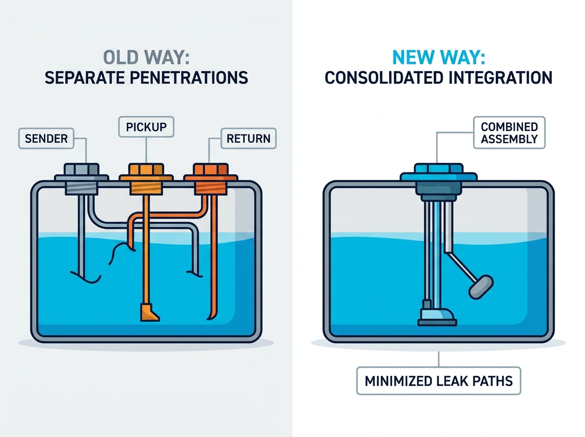
Modern fluid management strongly favors replacing separate tank penetrations with a consolidated architecture. You no longer need three distinct holes for feeding, returning, and monitoring fuel. Auxiliary generator installations frequently encounter severe physical space constraints. Marine, RV, and commercial backup scenarios also experience heavy environmental vibrations. Meeting rigorous safety compliance standards makes drilling multiple tank holes a significant liability. Every extra hole increases your leak risk and gasket degradation over time.
Upgrading to a combined assembly simplifies your system safely. However, doing so requires matching precise electrical resistance values to your display gauge. You must also manage fluid dynamics carefully to prevent harmful fuel aeration. Finally, navigating strict environmental containment regulations remains paramount. We will explore how to engineer a durable, compliant fluid management system. You will learn specific evaluation criteria, material selection strategies, and common implementation risks to avoid during your next installation.
Key Takeaways
Consolidating the sender, pickup, and return minimizes tank penetrations, actively reducing the risk of fuel leaks and vapor emissions.
Diesel and gasoline gensets require different return-line architectures; diesel returns must be submerged to prevent fuel foaming and aeration.
Accurate gauge integration depends on verifying the sender’s output signal (e.g., 240-33 Ohms vs. 0-190 Ohms) prior to installation.
A well-specified generator fuel pickup and return assembly must leave adequate clearance at the tank bottom to avoid pulling sludge or condensation into the fuel filter.
The Engineering Case for a Combined Fuel Sender for Genset Tanks
Engineering a reliable fuel system requires eliminating unnecessary vulnerabilities. Traditional designs often spread components across the top of a tank. They utilize a distinct sender unit, a separate feed line, and an isolated return line. You can streamline this entire layout by integrating a combined fuel sender for genset tank.
Minimizing Points of Failure
Reducing tank penetrations directly improves system reliability. Transitioning from three separate flanges down to one single mounting plate mitigates gasket degradation. Every rubber or cork gasket eventually succumbs to thermal cycling and chemical exposure. Fewer seals mean fewer potential leak paths. This consolidation prevents vapor emissions in enclosed spaces. It also ensures structural rigidity against heavy mechanical vibration.
Space and Structural Integrity
Auxiliary generator tanks often reside in tight chassis compartments. You might install them beneath an RV floor or inside a crowded boat hull. Surface area is severely limited in these custom configurations. Baffles welded inside the tank further restrict where you can safely drill. A consolidated sender unit requires only one flat mounting surface. This preserves the structural integrity of the tank roof. It allows manufacturers to design smaller, more efficient auxiliary fuel reservoirs.
Compliance and Safety Realities
Regulatory bodies enforce strict fuel containment protocols. The USCG dictates stringent marine standards. The RV industry follows specific NFPA guidelines for internal fuel storage. Meeting these codes becomes much simpler when you use a single, properly sealed flange. High-quality billet aluminum or 316 stainless steel flanges resist warping. They maintain a perfect seal under pressure testing. This compliance ensures your installation passes inspection and operates safely under extreme conditions.
Evaluating Gas vs. Diesel Requirements in Fluid Management
Fuel type fundamentally changes how you must handle fluid transfer. Diesel and gasoline possess entirely different chemical properties. They require tailored engineering approaches to maintain generator efficiency.
Diesel Return Line Dynamics
Diesel generators pull more fuel than they consume. They use the excess fluid to cool the internal injector components. The system then returns this heated fuel back to the primary tank. You must ensure the diesel return tube extends below the ambient fuel level. Dropping fuel from the top of the tank causes severe aeration. It whips the diesel into a foam. If the pickup tube ingests this aerated foam, it causes immediate injector cavitation. Submerging the return line eliminates this foaming risk entirely.
Gasoline Considerations
Gasoline generators face unique vapor management challenges. Gasoline is highly volatile and expands rapidly when heated. Modern emission standards demand completely sealed systems to trap these vapors. Additionally, electrical connections near gasoline vapor require strict explosion-proof ratings. You must select sending units featuring encapsulated reed switches. This completely isolates the electrical current from the combustible fluid.
Material Selection Evaluation
Material choices dictate the longevity of your entire assembly. We evaluate components based on their resistance to modern chemical blends.
Fluid Contact Materials Comparison
Material Type
Corrosion Resistance
Ethanol/Biodiesel Compatibility
Vibration Tolerance
Standard Plastics (Nylon/POM)
Moderate
Prone to swelling over time
High flexibility
Plated Carbon Steel
Low (Rusts easily)
Poor (Degrades quickly)
High rigidity
316 Stainless Steel
Maximum
Excellent (Zero degradation)
Superior durability
Upgrading to 316 stainless steel is almost always required for modern biofuels. Ethanol aggressively strips protective coatings from inferior metals. Biodiesel attracts water, leading to rapid bacterial corrosion. Stainless steel naturally resists these aggressive chemical attacks.
Core Evaluation Criteria for a Genset Fuel Level Sensor with Pickup and Return
You must calibrate the pickup tube length perfectly. The standard engineering rule dictates leaving exactly 1/2 to 1 inch of clearance from the tank floor. Water and heavy particulates naturally settle at the lowest point. If the tube touches the bottom, it immediately pulls this toxic sludge into your fuel filter. You must carefully measure the total internal depth. Always account for internal baffles. A baffle can easily block a sender unit if you measure incorrectly. Drop a rigid dowel rod into the flange hole to find the true unobstructed depth.
Electrical Output and Gauge Compatibility
Sender units translate fluid levels into electrical resistance. You face a high-risk compatibility issue here. The internal reed switches must match your external gauge perfectly. Industry standards generally fall into two distinct categories:
American Standard: 240 Ohms (Empty) to 33 Ohms (Full).
European Standard: 0 Ohms (Empty) to 190 Ohms (Full).
Mixing these up results in dangerously inaccurate readings. Connecting a European sender to an American gauge makes the needle read backwards. Always verify your digital control panel requirements before ordering.
Flow Rates and Fitting Dimensions
Fuel starvation happens when your tubing is undersized. You must analyze your generator's maximum Gallons Per Hour (GPH) consumption. Under heavy load, the genset demands high volumetric flow. The internal tube diameters of the sender must support this demand. Pay close attention to the NPT (National Pipe Thread) fitting sizes on top of the flange. Typical marine and RV units utilize 1/4-inch or 3/8-inch NPT threads. Selecting tubing that is too narrow restricts flow, causing the generator to surge or stall.
Implementation Risks: Wiring, Sealing, and Grounding
Even a perfectly specified generator fuel pickup and return assembly can fail during installation. You must strictly control how the unit connects to its surrounding environment.
Electrical Connector Vulnerabilities
Erratic gauge bouncing almost always stems from poor wiring. Sender units rely on a clean electrical ground to function correctly. Many installers mistakenly ground the unit to a painted chassis part. Paint acts as an insulator, disrupting the resistance signal. You must route a dedicated ground wire directly back to the common negative bus bar. Furthermore, always use marine-grade heat-shrink connectors. Moisture easily creeps into standard crimp terminals, accelerating copper corrosion.
Gasket and Fastener Protocols
Fuel containment relies entirely on proper gasket compression. You must specify fuel-rated materials like Viton or FKM. Standard nitrile rubber degrades quickly when exposed to modern ethanol blends. The industry standard utilizes a 5-hole SAE mounting pattern. This pattern is intentionally asymmetric. It forces you to align the sender in only one correct orientation. When tightening the machine screws, always use a star-pattern torque sequence. Tightening one side completely before the other warps the flange, creating an immediate vapor leak.
Siphon Breaks and Line Routing
Gravity-prone installations carry massive safety risks. If your generator sits lower than the fuel tank, you face a siphoning hazard. A severed fuel line would allow the entire tank to drain into the bilge or onto the ground. You must install mechanical anti-siphon valves directly at the withdrawal point. These spring-loaded check valves require engine vacuum to open. They physically prevent fuel from flowing freely if a line breaks. Additionally, always route your hoses away from extreme heat sources to prevent vapor lock.
Shortlisting Logic: Selecting the Right Assembly for Your Operation
Navigating the hardware market requires a systematic approach. You must align the product specifications with your precise environmental realities.
Application Alignment
Categorize your options based on environmental exposure. A marine-grade unit demands completely different weatherproofing than a standard enclosed RV chassis. Marine units require 316 stainless steel to survive saltwater atmospheres. They also demand IP67-rated electrical plugs. Conversely, a unit mounted inside a dry commercial truck frame may function perfectly well using durable billet aluminum components. Match the metal to the micro-climate.
Custom vs. Adjustable Units
You face a choice between fixed-length and universally adjustable assemblies. Fixed-length units are custom-ordered to your exact tank depth. They feature zero moving structural parts. This makes them highly resistant to severe vibration. Adjustable units offer great convenience. They allow you to cut the tubes to length on-site. However, adjustable sleeves or sliding brackets can vibrate loose over time. For heavy-duty industrial or off-road applications, fixed-length custom tubes provide superior reliability.
Vendor Verification
Examine the manufacturer's engineering documentation carefully. Trustworthy vendors publish exact resistance curves for their products. They clearly state compliance with USCG, ABYC, or CE certifications. Look closely at the warranty covering the internal reed switches. These microscopic glass switches do the actual measuring. High-quality vendors test their reed arrays for millions of cycles. Avoid unbranded units that lack detailed material specification sheets.
Conclusion
Moving to a consolidated fluid management architecture dramatically improves system safety. You minimize the number of tank penetrations, which drastically reduces leak risks. Consolidating the sender, feed, and return lines onto a single flange optimizes tight installation spaces. It also simplifies your compliance with stringent environmental containment codes.
Successful implementation depends entirely on dimensional and electrical precision. You must carefully calculate internal tube diameters to prevent fuel starvation. You also need to verify that your return lines remain submerged to eliminate aeration. Matching the specific Ohms range to your gauge remains a critical non-negotiable step.
Your immediate next step is taking physical measurements. Remove your existing hardware and measure the unobstructed depth of your tank. Then, consult your digital control panel's manual to confirm the required electrical resistance standard. Armed with this data, you can specify an accurate, reliable unit for your generator.
FAQ
Q: Does the return tube need to be the same length as the pickup tube?
A: The return tube is typically slightly shorter than the pickup tube. However, especially in diesel applications, it must extend far enough to remain permanently submerged in the fuel. Dropping fuel onto the surface from above causes aeration and foaming, which severely damages diesel injectors.
Q: Can I use a 0-190 Ohm sender on a 240-33 Ohm gauge?
A: No. Doing so will result in inverted or completely inaccurate readings. When the tank is full, the gauge will read empty, and vice versa. You must match the sender's resistance range precisely to the specific requirements of your display panel.
Q: Why is my genset stalling even with a new combined fuel sender?
A: Stalling usually indicates fuel starvation. Your pickup tube might be resting flush against the tank bottom, occluding the flow. Alternatively, the internal line diameter might be undersized for your generator's GPH demand. It could also indicate a vacuum lock caused by a malfunctioning anti-siphon valve.
Q: What is the standard mounting pattern for these combined assemblies?
A: The industry utilizes the standard SAE 5-hole mounting pattern. This bolt pattern is intentionally asymmetric. The unequal spacing guarantees you can only align and insert the sender unit in one specific orientation, preventing incorrect installation.
Top-rated designer and manufacturer of level-sensor and float-switch