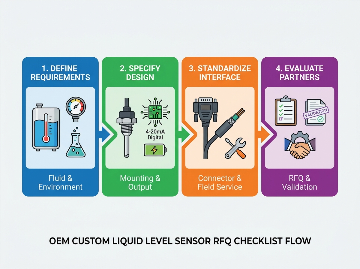
Vague sensor requests silently drain engineering budgets. They spark vendor miscommunications and derail product launch timelines. Prolonged prototyping cycles often follow poorly defined technical scopes. Transitioning from standard off-the-shelf components to a custom liquid level sensor demands absolute clarity. You cannot rely on assumptions when designing critical fluid monitoring systems. Every missing parameter introduces failure risks into your final equipment.
We created this definitive Request for Quotation (RFQ) checklist. It empowers engineering and procurement teams to lock down precise specifications early. You will learn how to document tank environments, mechanical mountings, electrical outputs, and connector details flawlessly before contacting manufacturers.
Key Takeaways
Accurate custom tank sensor design requirements must account for fluid dynamics, tank material, and environmental compliance from day one.
Electrical outputs and connectors must be specified with both system integration and long-term field troubleshooting in mind.
Mechanical mounting requires strict definition of thread standards, sealing mechanisms, and vibration tolerances to prevent field failures.
Vendor evaluation should heavily weight a manufacturer’s ability to provide transparent testing data, failure mode analysis, and scalable production validation.
Defining Custom Tank Sensor Design Requirements: Media and Environment
Every reliable fluid measurement system begins by analyzing the target media. Developing precise custom tank sensor design requirements requires evaluating fluid behaviors meticulously. You must document exact chemical compatibility. Identify the fluid pH, dynamic viscosity, and specific gravity. Note any presence of particulate matter, scaling deposits, or heavy sludge. Particulates easily clog unprotected pressure ports. Heavy sludge restricts mechanical floats. You must share these exact fluid realities in your RFQ.
Thermal and pressure baselines dictate structural sensor design. Specify continuous operating temperatures clearly. Do not confuse normal operating heat limits and peak thermal shock limits. A sensor might survive 80°C continuously but fail during a rapid 120°C cleaning flush. Next, define standard operating pressure alongside the maximum burst pressure. Pressure spikes happen during pump surges. Engineering teams must anticipate these transient events.
Tank architecture heavily influences sensor selection. Detail whether you use a closed or open tank system. Closed tanks require differential pressure (DP) compensation. Open tanks naturally vent atmospheric pressure. You should also note structural tank materials like Stainless Steel or Polyethylene. Plastic tanks pose unique grounding challenges. Metallic tanks introduce galvanic corrosion risks when paired with incompatible sensor housings.
Compliance foresight prevents sudden regulatory roadblocks. Include necessary industry certifications in your initial RFQ document. Aboveground Storage Tank (AST) regulations dictate strict spill prevention standards. Environments facing explosive vapor risks need Intrinsically Safe or ATEX certifications. Food and beverage applications require FDA or 3-A sanitary standards. Vendors must know these constraints before quoting a design.
Fluid Characteristics and Design Impact Chart
Fluid Characteristic
Engineering Consideration
Typical Sensor Adaptation
High Viscosity / Sludge
Risk of mechanical jamming or port clogging.
Non-contact ultrasonic or flush-diaphragm designs.
Extreme pH Levels
Rapid corrosion of standard metallic probes.
PTFE, PVDF, or specialized Hastelloy housings.
Varying Specific Gravity
Inaccurate readings in pressure-based units.
Guided wave radar or capacitive compensation.
Formulating the OEM Level Sensor Specification for Mechanical Mounting
Mechanical integration failures happen frequently when engineers overlook mounting constraints. Drafting a rigid OEM level sensor specification prevents costly machining reworks. You must establish the mounting orientation first. Decide between top, side, or bottom mounting approaches. Top-mounted sensors avoid direct fluid pressure leaks but require longer probe lengths. Side-mounted units save vertical space but face direct static head pressure. You must also account for internal tank obstructions. Identify internal baffles, heating coils, or agitation equipment. Agitators create turbulent surface waves. Baffles interfere with ultrasonic signal cones.
To avoid regional machining mismatches, follow these standardization steps carefully:
Select the specific thread standard: Explicitly define thread types like NPT (National Pipe Taper), BSP (British Standard Pipe), or SAE straight threads. Mixing NPT and BSP threads causes immediate fluid leaks.
Determine the sealing mechanism: Specify how the sensor seals against the tank wall. Choose between compressed O-rings, threaded sealants, or welded sanitary flanges.
Identify material compatibility for seals: Standard nitrile rubbers degrade quickly in diesel or chemical tanks. Specify chemical-resistant elastomers like Viton or EPDM based on the media analysis.
Physical durability ensures survival in harsh field applications. Mobile OEM equipment faces constant mechanical shock. Specify strict requirements for vibration resistance. Heavy machinery sensors require robust potting compounds to protect internal electronics from shaking. Finally, define stem or probe length tolerances. A probe cut two millimeters too long might strike a tank baffle during operation.
Selecting the Right Electrical Output and Signal Architecture
Your electronic control unit dictates the required output signal typology. Choose and justify the output format based on system architecture. Analog and digital signals serve different operational purposes.
Analog Signals (4-20mA, 0-5V, 0-10V, Ratiometric): The 4-20mA standard dominates industrial environments. It resists voltage drops over long cable runs. Voltage outputs suit short-distance circuits inside enclosed cabinets. Ratiometric outputs scale directly alongside input supply voltage fluctuations.
Digital Protocols (I2C, RS-485, CAN bus): Digital signals transmit complex multi-variable data. CAN bus excels in mobile heavy machinery and automotive sectors. RS-485 Modbus networks allow daisy-chaining multiple sensors across large industrial tank farms.
Power budgets dictate remote monitoring feasibility. Detail exact input voltage ranges. Specify maximum current draw explicitly. Battery-operated or solar-powered remote tank telemetry systems demand ultra-low power consumption. A sensor drawing 50mA continuously will drain a small remote battery rapidly. Request sleep-mode capabilities or intermittent polling features for remote sites.
Electromagnetic interference (EMI) ruins signal stability. Specify required EMI and RFI (Radio Frequency Interference) shielding. Sensors operating near high-voltage industrial pumps absorb electrical noise. Variable frequency drives (VFDs) generate massive electromagnetic distortions. Robust grounding cables, internal filtering capacitors, and shielded metal housings protect the raw level signal from nearby equipment noise.
Connector Standardization and Field Maintainability
Electrical connectors represent the most common failure point in industrial instrumentation. Environmental protection ratings must match reality. You must specify the exact IP (Ingress Protection) or NEMA rating. Match this rating to the actual operating environment. Washdown areas inside food processing plants require IP67 or IP69K ratings. Underground vaults facing continuous submersion demand true IP68 sealed designs. Do not over-specify ratings needlessly, but never under-specify for wet environments.
Connector typology directly impacts assembly speed on your OEM production line. Specify industry-standard connectors whenever possible. Standard M12, Deutsch, or Packard connectors guarantee reliable, weatherproof seals. Avoid proprietary plugs unless strictly necessary. If you require custom wire harnesses, document every detail. Provide exact cable lengths. Specify wire gauge (AWG). Choose the correct outer jacket material. Polyurethane (PUR) resists oils and mechanical abrasions beautifully. Polyvinyl Chloride (PVC) offers cost-effective protection for benign indoor applications.
Maintenance and troubleshooting foresight keeps end-users happy. Standardized wiring pinouts allow field technicians to replace damaged units blindly. Demand built-in diagnostic features. Request error-state signaling directly from the sensor. For example, program a 4-20mA sensor to output exactly 3.5mA during a hardware fault, and 4.0mA when the tank is completely empty. This simple logic distinction simplifies future troubleshooting. It tells the operator instantly whether the tank needs filling or the sensor needs replacing.
Evaluating Vendor RFQ Responses: Shortlisting Logic and Next Steps
Receiving vendor quotes initiates the critical evaluation phase. Price alone never tells the whole story. Look deeply into their engineering competence. Prioritize vendors who push back on conflicting specifications. An expert manufacturer will reject impossible tolerance requests. They offer design-for-manufacturability (DFM) improvements proactively. A vendor who blindly accepts flawed requirements will deliver flawed prototypes.
Prototype and tooling economics require total transparency. Demand clear breakdowns of all upfront charges. Identify Non-Recurring Engineering (NRE) costs. Separate custom mold or tooling fees from standard unit prices. Clarify prototype lead times before committing. Knowing exactly how long tooling takes prevents unexpected production line delays.
Validation and quality assurance metrics separate premium partners from basic machine shops. Look for vendors providing documented Mean Time Between Failures (MTBF) calculations. Ask for comprehensive failure mode and effects analysis (FMEA) reports. Request sample end-of-line calibration certificates. Real engineering partners prove their reliability through rigorous testing data. They do not guess.
Your actionable next step involves finalizing the initial RFQ package. Consolidate your fluid, mechanical, electrical, and connector data. Attach preliminary CAD models or tank diagrams if available. Distribute this comprehensive package to a shortlisted matrix of three or four specialized OEM manufacturers. This structured approach guarantees accurate, directly comparable proposals.
Conclusion
A meticulously detailed RFQ protects your organization from downstream delays. It eliminates the guesswork usually surrounding custom instrumentation. Defining exact fluid parameters, mechanical constraints, electrical architectures, and environmental realities ensures your final product functions flawlessly.
The goal extends beyond simply purchasing a component. You are establishing a scalable manufacturing partnership. This partnership relies entirely on clear, evidence-based engineering requirements. Taking the time to document every detail upfront removes friction from the prototyping phase.
Take action today by standardizing your internal engineering requests. Use this checklist framework to review your current preliminary specifications. Cross-reference your tank diagrams against your electrical connector requirements before sending your next vendor inquiry.
FAQ
Q: What is the typical lead time for a custom liquid level sensor prototype?
A: Standard prototyping timelines usually range from 4 to 8 weeks. This timeframe depends heavily on raw material availability and custom tooling complexity. Simple modifications to existing designs take less time. Highly specialized housings or custom-molded connectors push timelines toward the longer end of this spectrum.
Q: How do we handle Minimum Order Quantities (MOQs) in the RFQ phase?
A: Advise vendors of your expected annual usage (EAU) directly in the RFQ. Instead of accepting strict upfront MOQs, ask manufacturers for tiered pricing structures. This approach allows you to order smaller batches during early production rollouts while securing better pricing as your manufacturing volume scales up.
Q: Should we specify the sensor technology (e.g., ultrasonic vs. float) or let the vendor recommend it?
A: We suggest defining the specific business and environmental problem first. Detail the media, temperature, pressure, and tank shape accurately. Let the vendor propose the most reliable technology based on those facts. Evaluating their technical recommendation serves as an excellent test of their practical industry expertise.
Top-rated designer and manufacturer of level-sensor and float-switch